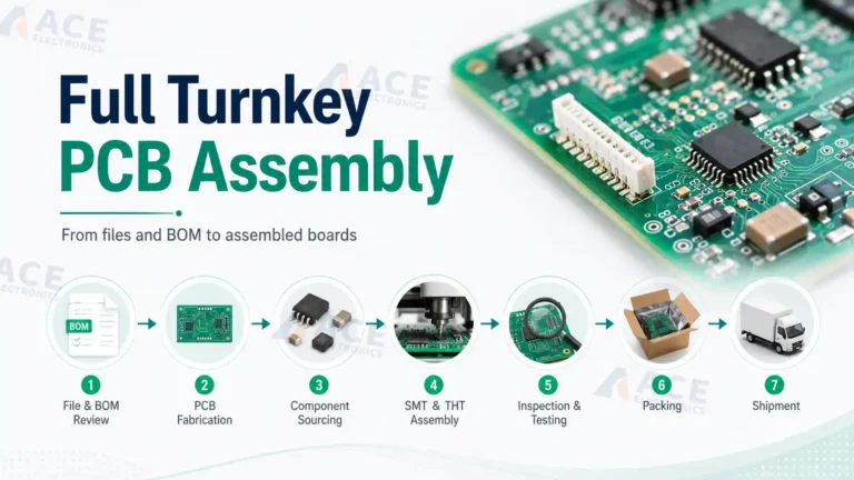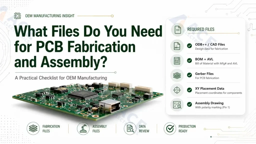
For PCB fabrication and assembly, most OEM projects need Gerber and drill files for the bare board, a BOM for component sourcing, a pick-and-place file for SMT placement, and assembly drawings for orientation and special instructions. More complex PCBAs may also need stackup data, fabrication drawings, test procedures, programming files, and revision notes.
The goal is to send one consistent manufacturing package that lets your contract electronics manufacturer quote accurately, source the right parts, assembly correctly based on your design, and test the finished PCBA.
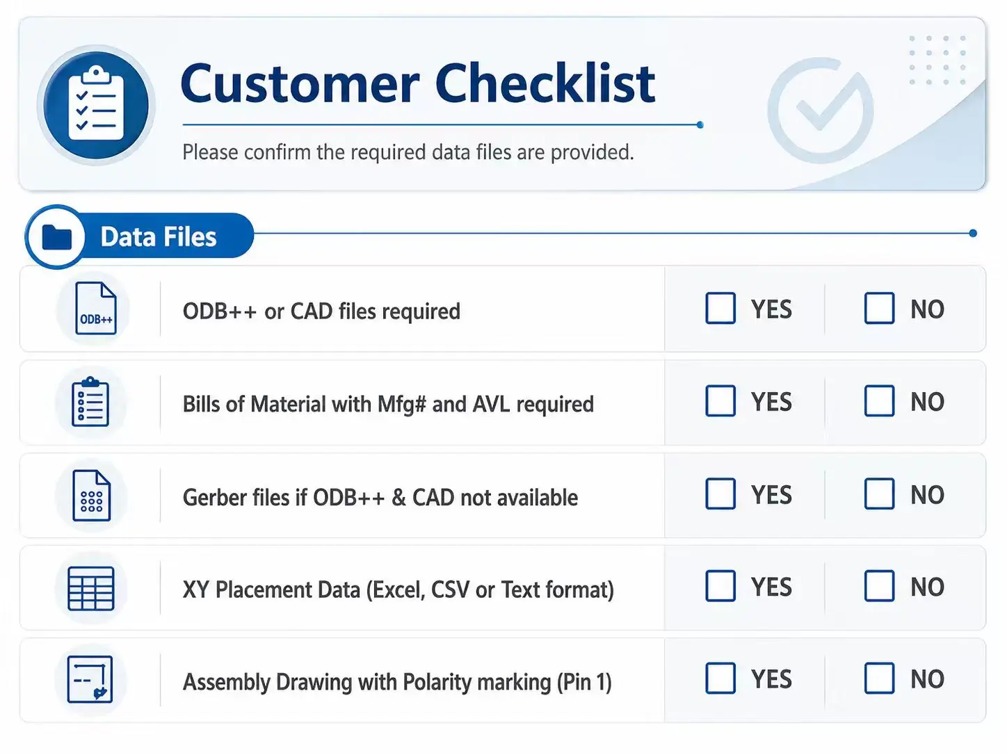 Alt: PCB assembly files checklist showing Gerber, BOM, pick-and-place, fabrication drawing, assembly drawing, and test files.
Quick Checklist: PCB Assembly Files for an OEM Build
Use this checklist when preparing files for a PCB fabrication and assembly quote.
| File or document | Needed for | What it should answer | Typical format |
|---|---|---|---|
| Gerber files | PCB fabrication, stencil, SMT review | What copper, solder mask, silkscreen, paste, and board outline should be produced? | .gbr, .gtl, .gbl, .gts, .gbs, .gto, .gbo, .gko, ZIP |
| NC drill files | PCB fabrication | Where are plated and non-plated holes, vias, slots, and mounting holes? | Excellon, .drl, .txt |
| Fabrication drawing | PCB fabrication | What board construction, dimensions, stackup, tolerances, impedance, and special notes apply? | |
| BOM | Component sourcing and assembly | Which exact components are approved for each reference designator? | .xlsx, .csv |
| Pick-and-place file | SMT assembly | Where should each SMT component be placed, on which side, and at what rotation? | .csv, .txt, .pos |
| Assembly drawing | PCBA assembly and inspection | How should polarity, orientation, labels, hardware, and special assembly notes be interpreted? | |
| Test procedure | PCBA testing | What should be tested, how, and what result is acceptable? | PDF, spreadsheet, test spec |
| Programming files | IC programming and validation | Which firmware, config file, or serial data should be loaded? | Binary, HEX, ELF, ZIP, readme |
| Revision notes | Quote control and production release | Which file revision is approved for this build? | TXT, PDF, readme |
PCB Fabrication Files vs PCB Assembly Files
PCB fabrication files describe the bare printed circuit board. PCB assembly files describe the components, placement, orientation, inspection requirements, and test instructions needed to turn that bare board into a working PCBA.
| Build stage | Main output | Core files | Common risk if incomplete |
|---|---|---|---|
| PCB fabrication | Bare PCB | Gerber, NC drill, fabrication drawing, stackup | Wrong outline, missing holes, incorrect layer stack, impedance mismatch |
| PCB assembly | Populated PCBA | BOM, pick-and-place, assembly drawing, test/programming files | Wrong component, wrong orientation, placement mismatch, incomplete test coverage |
| Turnkey PCBA | Finished assembly from one partner | Full fabrication + assembly + sourcing + testing package | Quote delays, sourcing substitutions not approved, build held for engineering clarification |
For a simple bare board order, Gerber and drill files may be enough. For PCBA contract manufacturing, the assembly partner usually needs BOM, pick-and-place, drawings, and any test or programming requirements as well.
1. Gerber Files: The Bare Board Manufacturing Data
Gerber files define the physical PCB layers used in PCB fabrication. They tell the fabricator how to produce the copper, solder mask, silkscreen, paste openings, and board outline. For new projects, use RS-274X (Extended Gerber), the standard Gerber format used by most PCB manufacturers.
A typical Gerber package includes:
| Gerber layer | Common file format | What it describes | Why it matters |
|---|---|---|---|
| Top copper | .GTL |
Top-side traces and pads | Defines electrical routing and SMT pads |
| Bottom copper | .GBL |
Bottom-side traces and pads | Defines routing and bottom-side pads |
| Inner copper layers | .G1, .G2, etc. |
Internal signal, power, and ground layers | Required for multilayer boards |
| Top solder mask | .GTS |
Top-side mask openings | Controls exposed pads and solderable areas |
| Bottom solder mask | .GBS |
Bottom-side mask openings | Controls exposed pads and solderable areas |
| Top silkscreen | .GTO |
Top-side markings and designators | Helps inspection, polarity, and manual review |
| Bottom silkscreen | .GBO |
Bottom-side markings and designators | Useful for double-sided assemblies |
| Top solder paste | .GTP |
Top-side stencil apertures for SMT solder paste | Required for top-side SMT stencil fabrication |
| Bottom solder paste | .GBP |
Bottom-side stencil apertures for SMT solder paste | Required for bottom-side SMT stencil fabrication |
| Board outline | .GKO, .GML, or outline layer |
Final PCB shape | Prevents outline, slot, and routing errors |
The solder paste layers are especially important for SMT assembly. These files are used to make the SMT stencil, which controls where solder paste is deposited before component placement and reflow. If a board has SMT components on the top or bottom side, the matching paste layer should be included in the released Gerber package.
Gerber File Checks Before Release
Before sending Gerbers to your PCB assembly partner, engineering teams should check:
- All copper, solder mask, silkscreen, paste, and outline layers are included.
- Board outline is clear and closed.
- Top and bottom layers are not mirrored incorrectly.
- Solder paste layers exist for SMT sides that need stencil printing.
- Silkscreen does not cover exposed pads.
- Fiducials, tooling holes, and panel features are included if required.
- Gerber revision matches the BOM and pick-and-place revision.
For designs with fine-pitch ICs, BGAs, dense connectors, or mixed SMT and through-hole assembly, file consistency should be reviewed before RFQ.
2. NC Drill Files: Holes, Vias, and Slots
NC drill files identify hole locations, hole sizes, plated holes, non-plated holes, and sometimes slots. They are normally exported with the fabrication data and are required for the bare PCB.
The drill files should show:
- Plated through holes and vias.
- Non-plated mounting holes.
- Slots, cutouts, and routed features.
- Finished hole sizes.
- Drill units and coordinate format.
- Whether separate plated and non-plated drill files are provided.
Missing or incorrect drill files can affect electrical connectivity, connector fit, mechanical mounting, and through-hole assembly. If your board uses press-fit connectors, large mechanical hardware, or connector shells tied to chassis, confirm the finished hole size and tolerance in the fabrication drawing as well.
3. Fabrication Drawing: Details Gerber Files Do Not Fully Explain
A fabrication drawing is a controlled PDF that explains construction requirements that may not be obvious from Gerbers alone. It is especially important for multilayer, controlled impedance, rigid-flex, high-current, RF, industrial, automotive, or medical electronics projects.
Include a fabrication drawing when the board has:
- Specific total thickness or layer stackup.
- Controlled impedance requirements.
- Material or Tg requirements.
- Copper weight requirements.
- Finished hole tolerances.
- Slots, cutouts, castellations, bevels, or edge features.
- Panelization requirements.
- IPC class requirements.
- Serialization, date code, UL marking, or customer marking requirements.
| Fabrication drawing item | Why customers should specify it |
|---|---|
| Board dimensions and tolerances | Prevents fit issues with enclosures, connectors, and mounting hardware |
| Layer stackup | Controls thickness, impedance, and manufacturing assumptions |
| Copper weight | Affects current capacity, etching limits, and cost |
| Material callout | Controls thermal, mechanical, and reliability expectations |
| Controlled impedance notes | Prevents signal integrity surprises after fabrication |
| Hole and slot details | Prevents connector and mechanical fit problems |
| Panelization notes | Helps quote and build the same production format |
If your project needs both bare board manufacturing and assembly, the fabrication drawing should be consistent with the assembly drawing. For example, board edge features, tooling holes, labels, and panel rails should not contradict each other.
4. BOM: The Component Sourcing and Assembly List
The BOM tells the assembly partner which parts belong on the PCBA. For turnkey assembly, it also drives component sourcing, price, lead time, alternates, and supply risk.
At minimum, a PCB assembly BOM should include:
| BOM field | Purpose |
|---|---|
| Reference designator | Maps each part to a PCB location, such as R12, C4, U1 |
| Quantity per board | Prevents under-buying or over-buying components |
| Manufacturer part number | Identifies the exact approved component |
| Manufacturer | Reduces ambiguity when multiple suppliers use similar numbers |
| Description or value | Helps engineering review and sourcing validation |
| Package or footprint | Confirms assembly compatibility |
| Approved alternates | Allows controlled substitution when supply changes |
| DNI or DNP status | Identifies parts that should not be installed |
| Customer-supplied or turnkey status | Clarifies who provides each part |
Do not rely on vague descriptions such as "10k resistor" or "USB connector" for production builds. Those descriptions may be useful for humans, but they are not enough for procurement, incoming inspection, or repeat manufacturing.
BOM Risks That Delay PCB Assembly
Most delays happen because key sourcing information are missing in BOM, such as exact part numbers, approved alternates, or DNI/DNP status.
| BOM problem | What can happen |
|---|---|
| Missing manufacturer part number | Sourcing team must guess or ask for clarification |
| Reference designators do not match placement file | Engineering review stops until files are reconciled |
| Obsolete or unavailable component | Quote changes, lead time increases, or alternate approval is needed |
| No approved alternates | Production is blocked if a part is unavailable |
| Unclear DNI/DNP parts | Wrong parts may be installed or quoted |
| Mixed prototype and production revisions | Cost, sourcing, and assembly assumptions become unreliable |
If your project depends on scarce ICs, qualified alternates, or customer-approved suppliers, connect the BOM review with component sourcing in advance.
5. Pick-and-Place File: Component Position and Rotation
A pick-and-place file, also called a centroid file, CPL file, XY file, or component placement file, gives the assembly partner machine-readable placement data for SMT parts. Common formats include .csv, .txt, and .xls or .xlsx; the file extension matters less than clear columns and consistency with the BOM and Gerber revision.
For SMT assembly, the pick-and-place file usually includes:
| Field | What it means |
|---|---|
| Reference designator | Component ID that must match the BOM |
| X coordinate | Horizontal component center location |
| Y coordinate | Vertical component center location |
| Rotation | Component orientation in degrees |
| Side or layer | Top or bottom side of the PCB |
| Package or footprint | Helpful for cross-checking placement and BOM data |
6. Assembly Drawing: Orientation, Polarity, and Special Notes
An assembly drawing helps humans interpret the build. It is not a replacement for the BOM or pick-and-place file, but it is useful for review, inspection, rework, and special assembly instructions.
An assembly drawing should show:
- Component outlines.
- Reference designators.
- Polarity and pin 1 indicators.
- Connector orientation.
- LED and diode direction.
- Mechanical hardware, shields, heat sinks, or stiffeners.
- Labels, stickers, barcodes, and serial number positions.
- Special instructions for hand-installed or post-reflow items.
- Any parts installed after cleaning, testing, or conformal coating.
For through-hole assembly, the assembly drawing should be especially clear about connector orientation, component height, lead forming, hardware, and solder-side constraints.
If the silkscreen is crowded, do not assume the assembler can infer orientation from the PCB image. A clean PDF assembly drawing is often the easiest way to remove ambiguity.
7. Stackup, Impedance, and Panelization Information
Stackup and panelization information may not be required for every prototype, but it becomes important when electrical performance, mechanical fit, or production handling matters.
Provide stackup information when the board has:
- Four or more layers.
- Controlled impedance traces.
- RF, high-speed digital, or differential pairs.
- Specific dielectric thickness requirements.
- Rigid-flex or flex sections.
- High-current copper requirements.
Send panel files or panel instructions when:
- You already approved a production panel.
- The board shape is irregular.
- Edge connectors, castellation, breakaway tabs, or routing direction matter.
- You need specific rail, fiducial, or tooling-hole locations.
- The same panel must be used for test fixtures or automated handling.
If you want the assembly partner to panelize the board, say so in the RFQ. If your team has already approved the panel, send the released panel Gerbers and panel drawing.
8. Test, Programming, and Quality Documents
Testing files are not always part of the initial PCB file checklist, but they matter for OEM projects because a visually correct PCBA may still fail functionally.
For production-oriented PCB assembly files, include test and programming documents when applicable:
| Document | When to include it | What it should contain |
|---|---|---|
| Functional test procedure | Product must be powered and verified | Test steps, fixtures, pass/fail limits, required equipment |
| ICT or flying probe data | Electrical test points are available | Netlist, test pads, fixture notes, excluded nets |
| Firmware or programming file | MCU, FPGA, memory, or module must be programmed | File version, checksum, programming method, lock bits |
| Calibration instructions | Sensors, analog circuits, RF, or power products need calibration | Limits, adjustment steps, record format |
| Inspection criteria | Customer-specific workmanship requirements apply | Critical components, cosmetic rules, acceptance criteria |
| Labeling or serialization spec | Traceability is required | Label position, format, barcode rules, serial range |
If your PCBA requires firmware loading, serialization, or fixture-based testing, align this package with IC programming and testing early. It is easier to quote and validate testing before production release than after assemblies are already built.
9. Turnkey vs Consigned Assembly: File Package Differences
The PCB assembly files are similar for turnkey and consigned projects, but the level of sourcing detail changes.
| Build model | Customer provides | Assembly partner provides | File package focus |
|---|---|---|---|
| Turnkey PCB assembly | Released design files, BOM, approved alternates, test requirements | PCB fabrication, component sourcing, assembly, inspection, testing | Accurate BOM, sourcing approval, revision control |
| Consigned PCB assembly | Design files plus customer-supplied parts or kits | Assembly, inspection, testing, sometimes PCB fabrication | Kit list, part counts, part labeling, BOM-to-kit match |
| Partial turnkey | Some critical parts, some sourced parts | Sourcing for remaining parts plus assembly | Clear ownership by line item |
For turnkey builds, the BOM must be sourcing-ready. For consigned builds, the kit list must match the BOM, and any missing or extra materials should be resolved before assembly starts.
Common PCB Assembly File Mistakes and How to Prevent Them
| Mistake | Why it matters | Prevention |
|---|---|---|
| Sending Gerbers without drill files | Fabricator cannot confirm holes and vias | Export Gerber and Excellon drill together |
| BOM has descriptions but no MPNs | Sourcing becomes ambiguous | Use exact manufacturer and manufacturer part number |
| Pick-and-place file uses different reference designators than BOM | SMT program cannot be verified cleanly | Compare BOM and CPL before release |
| Polarity is unclear | Diodes, LEDs, ICs, and capacitors may be installed incorrectly | Use assembly drawing and silkscreen polarity marks |
| Top and bottom sides are mislabeled | Double-sided assembly errors can occur | Use consistent side naming across Gerber, CPL, and drawings |
| DNI parts are still in placement file | Non-installed parts may be quoted or installed | Mark DNI clearly and align BOM/CPL/drawing |
| Old file revision is mixed into the ZIP | Wrong PCB or wrong assembly can be built | Use one release folder and revision-controlled filenames |
| Test requirements are sent after quote | Cost and lead time may change | Include test scope during RFQ |
Recommended File Package Structure
For most OEM projects, send one ZIP file organized like this:
ProjectName_PCBA_RevA03_2026-04-29.zip
  01_Gerber_Drill/
  02_Fabrication_Drawing/
  03_BOM/
  04_Pick_and_Place/
  05_Assembly_Drawing/
  06_Test_and_Programming/
  07_Readme_Revision_Notes/
This structure helps purchasing, engineering, and the assembly partner review the same build package without relying on scattered email attachments.
When Should You Ask for a File Review?
Ask for a file review before quoting or production if the design includes:
- Fine-pitch ICs, QFNs, BGAs, or bottom-terminated components.
- Double-sided SMT assembly.
- Mixed SMT and through-hole components.
- Controlled impedance or high-speed interfaces.
- Customer-supplied parts.
- Programming or functional testing.
- Alternate components requiring approval.
- Production beyond a quick prototype quantity.
For early-stage builds, a short DFM and file-readiness review can reduce avoidable quote revisions. For repeat builds, it helps confirm that the new revision is truly ready for production.
Frequently Asked Questions
What files are needed for PCB assembly?
What files are needed for PCB assembly?
Most PCB assembly projects need Gerber and drill files, a BOM, a pick-and-place file, and an assembly drawing. Depending on the project, you may also need a fabrication drawing, stackup, panelization notes, test procedure, programming files, and revision notes.
Are Gerber files enough for PCB assembly?
Are Gerber files enough for PCB assembly?
Gerber files are enough for many bare PCB fabrication quotes, but they are not enough for full PCB assembly. Assembly also requires a BOM to identify components and a pick-and-place file to define component locations and rotations.
What is the difference between Gerber, BOM, and pick-and-place files?
What is the difference between Gerber, BOM, and pick-and-place files?
Gerber files describe the bare PCB layers. The BOM lists the components that must be installed. The pick-and-place file gives the X/Y position, rotation, and side for SMT components so the assembly partner can place parts accurately.
Do you need to provide pick-and-place file for PCB assembly?
Do you need to provide pick-and-place file for PCB assembly?
You should provide a pick-and-place file for SMT assembly. It reduces manual interpretation, helps verify component placement, and allows the assembler to cross-check the BOM against the PCB layout. For through-hole-only assemblies, it may be less critical, but drawings and BOM accuracy still matter.
What should be included in a PCB assembly drawing?
What should be included in a PCB assembly drawing?
A PCB assembly drawing should include component outlines, reference designators, polarity marks, pin 1 indicators, connector orientation, mechanical hardware, labels, and any special assembly notes that are not obvious from the BOM or placement file.
What files are needed for PCB fabrication vs PCB assembly?
What files are needed for PCB fabrication vs PCB assembly?
PCB fabrication usually needs Gerber files, NC drill files, and a fabrication drawing. PCB assembly needs the assembly data: BOM, pick-and-place file, assembly drawing, and any test or programming instructions needed to verify the finished PCBA.
Can a PCB assembler work with incomplete files?
Can a PCB assembler work with incomplete files?
Sometimes an assembler can help identify missing information, but incomplete files usually create quote delays, engineering questions, sourcing uncertainty, or build risk. For OEM projects, it is better to release one complete and consistent package before RFQ or production.
Conclusion
A reliable PCB assembly file package is not just a set of individual exports from PCB Design software. It is a controlled manufacturing package: Gerbers and drill files for the board, BOM for parts, pick-and-place for SMT placement, drawings for interpretation, and test documents for final validation.
If you have demand of electronics assembly service, ACE Electronics can review the file package through its PCBA contract manufacturing workflow and help align fabrication, sourcing, assembly, and testing requirements before production starts.
About the Author
Bill Ho is Sales Engineer and Chief Editor at ACE Electronics, with 10 years of experience in PCB fabrication and PCB assembly.
He writes practical technical content focused on manufacturability review, fabrication communication, and assembly risk reduction.