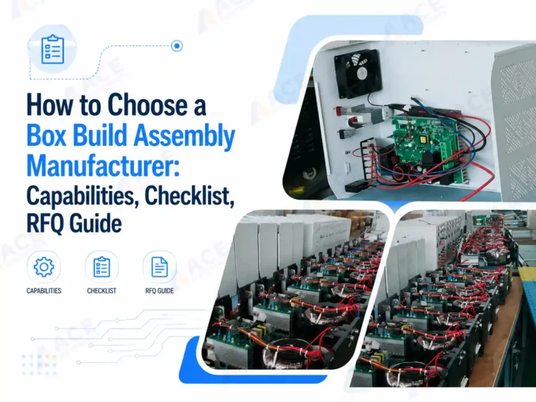
box build assembly takes tested PCBA and turns them into complete electronic products — ready to ship with enclosure assembled, cables connected, firmware loaded, labels applied, and functional testing completed. This is the step that turns assembled PCBs into the devices you or your customers can directly sell or use.
The decisions made during product design — enclosure choice, connector placement, cable routing paths, test point access — directly affect how much labor a box build assembly takes and how many problems surface on the production line. This guide covers what box build assembly involves, how design choices affect assembly cost and quality, and when a box build assembly makes sense for your product.
What Is Box Build Assembly?
Box build assembly is the process of integrating a tested PCBA with its enclosure, cables, wire harnesses, other electronics parts, connectors, firmware, labels, and packaging to produce a finished electronic product. It is sometimes called system integration or electromechanical assembly.
The work goes beyond mounting the board into a housing. Here is what box build assembly actually involves:
-
Enclosure and mechanical integration: The PCBA is mounted into a housing — sheet metal, plastic, or a custom injection-molded shell — with the right clearances, mounting holes, grounding, and thermal paths. Display windows, connector cutouts, and button openings are aligned and secured.
-
Display, battery, and connector integration: LCD screens, membrane switches, external connectors, and battery packs are installed and connected. These are often the parts the end user touches or sees, so fit and alignment matter.
-
Cable and wire harness routing: Internal cables are cut, terminated, routed, and secured. Poor cable routing is one of the most common causes of production rework, especially when the prototype phase skipped routing validation.
-
Potting and environmental sealing: For outdoor or harsh environments, the assembly may receive conformal coating, potting compound, or gasket sealing to protect against moisture, dust, and vibration.
-
firmware loading and configuration: We load the firmware you provide during PCB assembly. Version records and programming logs are kept when your project requires traceability.
-
System-level testing: Unlike board-level testing, this checks if the complete unit works — power-on behavior, button response, display output, battery charging, and communication port activity.
-
Labeling and packaging: Product labels, serial numbers, carton labels, accessories, and manuals are applied before the unit is packed for shipment.
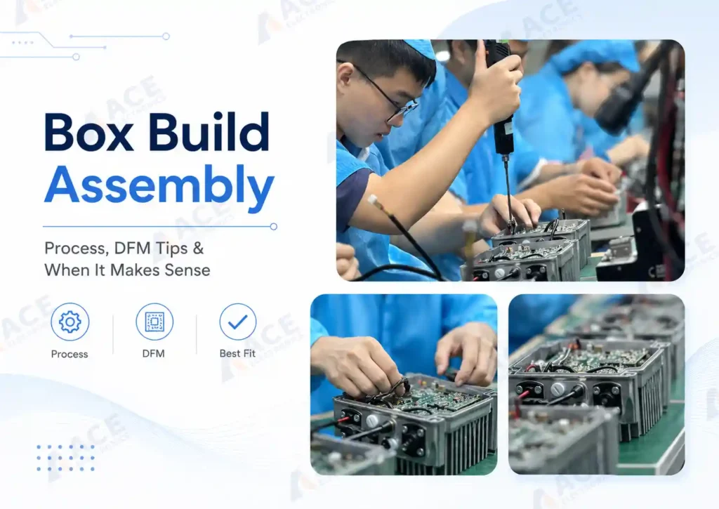
 A completed box build assembly integrating PCBA, cable harness, enclosure, firmware, and labeling.
Box Build Assembly vs PCB Assembly
PCB assembly produces a functional circuit board. Box build assembly produces a product. When you are deciding how much integration work to keep in-house and how much to hand off, the distinction matters.
| PCBA | Box Build Assembly | |
|---|---|---|
| What it delivers | A assembled & tested circuit board | A finished product your customer can sell or use right awaydevice |
| Core scope | Solder components, inspect, test | PCBA + enclosure + cables + firmware + labels + final test based on your projects' demand |
| Components involved | PCB, ICs, passives, connectors and other components that need to be soldered on PCB | All PCBA items plus enclosure, wire harnesses, brackets, display, fasteners, packaging |
| Testing level | Electrical (AOI, ICT, FCT for the board) | Electrical + functional + system-level testing |
| Files needed | Gerber, BOM, pick-and-place | All PCBA files plus assembly drawings, enclosure specs, wiring diagrams, test instructions |
Why Teams Choose Box Build Assembly Over Managing Multiple Suppliers
Most hardware teams face a simple choice: let one partner handle the full build, or split the work across multiple suppliers and manage the coordination yourself.
-
Fewer handoffs, fewer delays. One partner handles PCBA, cables, enclosure, firmware, and testing. No gaps between vendors. No miscommunication about cable specs or firmware versions that one shop missed. In an industrial energy storage inverter project, switching from separate PCBA, wire harness, and chassis assembly suppliers to one turnkey partner eliminated the coordination gaps between board assembly and final product testing — and the production has now run at 500 units per month for two years.
-
Revision control stays clean. One partner keeps your BOM, drawings, firmware, and test specs in sync. With split vendors, your enclosure shop might build to revision A while your PCBA supplier uses revision B. You find out on the production line, not in the design review.
-
Faster from pilot to volume. The same team runs your pilot build, fixes issues, and scales to production. You do not re-explain the design to new vendors or wait for separate suppliers to sync their schedules.
-
System-level quality, not just board-level. One partner tests the whole product. A PCBA can pass electrical test and still fail after enclosure assembly — a noisy cable, a loose connector, a shifted bracket. System-level testing catches what board-level testing misses.
-
Lower total cost when you count your own time. Box build unit price looks higher on paper. But add the hours you spend managing vendors, shipping between shops, troubleshooting integration issues, and fixing rework from miscommunication. For teams without a dedicated supply chain group, one partner is usually cheaper in total.
-
Scaling does not start from zero. The same partner handles 20 units or 2,000. No need to re-qualify suppliers, rebuild test fixtures, or rewrite procedures. The workflow is already proven.
Design Tips for Box Build Assembly
How you design the product determines how fast and cheap it is to assemble. Optimize the design and assembly sequence during the design phase. Build prototypes with your assembly partner, collect their feedback on fit, routing, and access, and fix issues before you move to volume. This saves assembly time, reduces field failures, and gets the product to market faster.
Enclosure: Standard First, Custom Only If You Must
Standard enclosures from suppliers like Hammond, Bud, or Rose come in thousands of sizes and are usually in stock. Custom enclosures add 12–20 weeks for first samples and often need iterations. Unless your product has unique form-factor or environmental needs, start with a standard box.
A box build partner with sourcing capability in China can help you find an off-the-shelf enclosure that fits your PCB size and connector layout — without paying for custom mold tooling. In May 2026, we sourced a standard enclosure locally for a client during their prototype phase. Just need minor PCB layout adjustments, and the project moved forward to mass production without the 6-8 week mold injection lead time or the upfront tooling cost.
This is especially useful during the prototype stage, when the design is still changing and you do not want to lock in a mold before the board layout is finalized.
Pick an enclosure that makes assembly easier:
- Built-in PCB mounting bosses — better than drilling and tapping custom holes
- Pre-formed cable entry points aligned with your connector layout
- Enough internal room — cramped assemblies are harder to build and take longer per unit
- Removable panels so the team can reach all mounting points
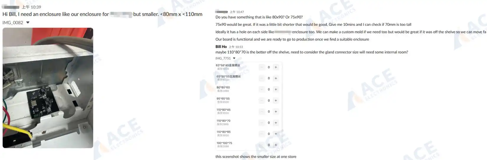 A Slack conversation with our US client reviewing enclosure dimensions, cable gland types, and BOM details before starting his new box build assembly production order.
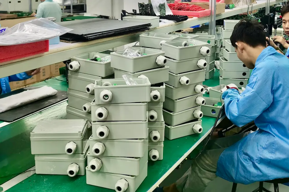
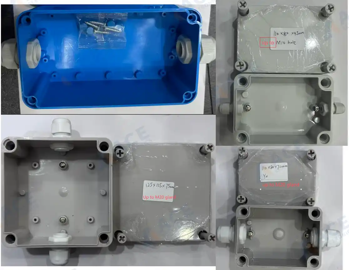 Off-the-shelf ASB enclosure samples with matched cable glands — sourced and reviewed with our client for prototype verification.
PCB Mounting and Connector Placement
Use standard mounting: brass or nylon standoffs, DIN rail clips, or card guides. Avoid custom brackets — they need fabrication and add steps.
Leave practical clearances around the PCB:
- 5–10 mm from enclosure walls for assembly tolerance
- Room above tall components — the board should slide in, not be forced
- All mounting points reachable with a tool
- Room at connectors so cables plug in without sharp bends
Pay attention to connector placement. External connectors should sit near panel cutouts. Internal connectors should face natural cable paths — not force 180-degree bends. A connector placed 2 mm from a wall with a cable that needs 25 mm bend radius is a preventable routing problem.
Cable Harness: Keep It Simple
Custom harnesses add time. Use standard parts when you can:
- Standard cables from distributors
- Modular cables in different lengths
- IDC connectors instead of hand-soldered ones
With multiple cables, label both ends or use different connector types so misconnection is physically impossible. Color coding helps for polarity. Unit 1 built without labels might be fine. Unit 50, built by a different operator, may have swapped cables.
Plan cable routing: tie-down points, strain relief at connectors, protection over sharp edges, and keep signal and power cables apart. Loose cables get damaged, slow assembly, and look unprofessional.
Thermal Management at the System Level
Many products overheat not because the components fail, but because the enclosure traps heat. Consider:
- Ventilation paths — can hot air escape?
- Fan mounts if you need forced cooling
- Heat sinks mounted to the enclosure to pull heat outside
- Keep heat-sensitive parts away from heat sources
Fix thermal issues in design. Adding fans and heat sinks to an already-packed assembly is expensive.
Documentation the Assembly Team Needs
Clear docs reduce time and prevent errors. You need:
- Assembly drawings — exploded views, assembly sequence, detail views for complex steps, torque specs, and cable routing
- BOM — part numbers, quantities, and who supplies what
- Test procedures — steps, pass/fail criteria, equipment needed, and calibration if applicable
Good docs let the team build correctly without calling you repeatedly. Poor docs cause errors, delays, and quality drift.
Common DFM Mistakes That Raise Cost
Inaccessible fasteners. A screw you cannot reach once the previous part is installed is a problem on every unit. Check that each step does not block the next.
Impossible cable routing. Paths that look clean in CAD may fail in reality due to bend radius or interference. A 3D model does not show how a real cable behaves.
Tolerance stack-up. Parts within individual tolerance may not fit together when stacked. What worked on prototype unit 1 may fail on unit 50 when supplier batches change.
Over-specification. Tight tolerances, exotic materials, or complex procedures add cost without value. Use standard fasteners, enclosures, and processes. Every non-standard element adds cost and lead time.
How the Box Build Assembly Process Works
-
1. RFQ Package and Requirement Review The BOM, assembly drawings, enclosure details, cable specifications, firmware files, test requirements, label artwork, packaging instructions, and target quantity are reviewed. Missing or unclear items are flagged before quoting — this is the stage where communication gaps cause the most delay.
-
2. Build Plan and Risk Check Key assembly points are confirmed: PCBA mounting method, cable routing paths, connector access, enclosure fit, label positions, test coverage, and packaging method. Design risks or tolerance concerns are raised now, not discovered on the production line.
-
3. Sample Build or Pilot Run For new projects, a sample or pilot run checks fit, wiring, fastening, firmware loading, functional testing, and final packaging before committing to the full production quantity. Issues found during a pilot run are far cheaper to fix than issues found mid-production.
-
4. Controlled Production Production runs follow the approved BOM, drawings, firmware version, assembly notes, test requirements, labeling rules, and packaging instructions. Revision control and change tracking keep the process consistent from unit to unit.
-
5. Final Inspection and Testing Every finished unit is checked against the agreed requirements — visual inspection, functional test, label verification, connector checks, and packaging confirmation.
-
6. Labeling and Packaging Product labels, carton labels, serial numbers, accessories, and manuals are applied. The finished units are packed and prepared for shipment.
What tests needed in Box Build Assembly
Testing at the box build stage goes beyond what happens at the board level. A PCBA can pass electrical test and still fail inside its enclosure — when cables introduce noise, a connector seats incompletely, or firmware behaves differently under full system load.
Functional Testing
Functional tests follow the pass/fail criteria defined in the test plan: power-on sequence, button response, display output, communication port activity, signal checks, and any customer-defined test steps. Test records are maintained when the project requires them.
Burn-In and Aging Tests
For products that must prove reliability over extended operation, burn-in or aging tests run the assembled unit under power for a set duration. This catches intermittent faults that brief functional tests miss — a solder joint that opens after thermal expansion, or a component that drifts after hours of operation. For industrial controllers and energy storage products, this step is often a standard part of the production flow.
Traceability and Documentation
Traceability — by work order, batch, or serial number — links each unit to its component lots, firmware version, test results, and operator records. For regulated industries or products with field service requirements, having these records available simplifies compliance audits, warranty claims, and failure investigations.
When Does Box Build Assembly Make Sense?
Box build assembly tends to be a good fit when:
- Your team develops products but does not run an in-house final assembly line
- The product needs more than a bare PCBA — enclosure, internal cabling, firmware, labeling, and packaging are all required
- Your annual volumes are in the hundreds to low thousands, where the fixed cost of setting up internal assembly is hard to justify
- You want fewer suppliers managing different parts of the integration, so that revision control and quality responsibility stay under one roof
- The product needs specialized processes — conformal coating, potting, environmental sealing, or multi-step calibration — that would require equipment investment if done in-house
- You need the finished unit to arrive tested and packaged, ready for your customer or distribution channel
Frequently Asked Questions
What is box build assembly?
What is box build assembly?
Box build assembly is the process of integrating a tested PCBA with its enclosure, cables, wire harnesses, connectors, firmware, labels, and packaging into a finished electronic product. It goes beyond PCB assembly by delivering a unit that is system-tested and ready for use or distribution.
What is the difference between PCBA and box build assembly?
What is the difference between PCBA and box build assembly?
PCBA delivers a functional circuit board. Box build assembly delivers a complete product inside an enclosure — with all cables routed, firmware loaded, labels applied, functional testing completed, and packaging done. The key difference is the level of integration: PCBA stops at the board; box build assembly goes to the finished device.
How does product design affect box build assembly cost?
How does product design affect box build assembly cost?
Design decisions — enclosure type, connector placement, cable routing, test point accessibility, and mounting methods — directly affect assembly labor time. A board with connectors positioned 2 mm from an enclosure wall takes more time to assemble than one with proper clearance. Standard enclosures cost less and arrive faster than custom ones.
Can firmware loading be included during box build assembly?
Can firmware loading be included during box build assembly?
Yes. Firmware can be loaded during the assembly stage when you provide the approved binary file, version rules, and programming method. Version records and programming logs are available when the project requires them.
How long does a box build assembly project take from RFQ to shipment?
How long does a box build assembly project take from RFQ to shipment?
The timeline depends on project complexity, enclosure and mechanical part availability, production quantity, and how complete the RFQ package is. Custom enclosures can add 12–20 weeks of lead time before assembly even begins. A well-prepared RFQ with clear drawings, BOM, test criteria, and labeling requirements helps the assembly partner respond with an accurate schedule faster.
Next Steps for Your Box Build Assembly Project
If you are planning a product that needs system-level integration beyond a bare PCBA, early preparation makes the RFQ process faster and the quote more accurate. Most assembly partners will need your BOM, Gerber files, assembly drawings, enclosure specifications, cable requirements, firmware files, test criteria, and labeling instructions.
For guidance on selecting the right production partner, read our article on how to choose a box build assembly manufacturer.
If you are ready to discuss a specific project, welcome to WhatsApp us or leave enquiry in following form.