On this page
In December 2025, When a power electrical company contacted us, they had a working design for a compact small energy storage device — a DC power conversion and control unit used inside a small-scale storage system. They had completed their engineering validation, had a finalized BOM, Gerber files, and assembly drawings, and needed to move into mass production. The fisrt order was 1000 units.
Their product had three kinds of material we needed to manage:
- Power PCBA — carrying transformers, inductors, large electrolytic capacitors, power MOSFETs, and board-side connectors
- Internal wiring harnesses — custom-length wires with connector terminals on both ends, running between the PCBA and external interface ports
- Custom aluminum enclosure — a palm-sized extruded aluminum housing with milled openings for connectors and ventilation, supplied by the customer
The customer had initially asked serveal suppliers for quotes, most of PCB assembly factories only quoted PCB assembly service, like SMT and THT. Nobody would take responsibility for assembling the finished unit, and nobody would run the finished-unit test.
That's why they came to us. They needed one partner to handle the full assembly process from PCBA through to tested, packaged finished products.
Key project parameters:
| Item | Detail |
|---|---|
| Order size | 1000 units |
| Product stage | Prototype validation completed, moving to production |
| Customer's initial problem | Multiple suppliers, no single factory for finished-unit assembly and test |
| Enclosure | Customer-supplied aluminum housing |
| Production goal | Component sourcing → PCBA → box build → functional test → aging test → packaging |
| Customer deliverables to us | BOM, Gerber files, schematic, assembly drawings, test specification, test program |
Our Full Manufacturing Scope
Here is exactly what our team covered:
| # | Stage | What we did | Why it mattered |
|---|---|---|---|
| 1 | Component sourcing | Procured all electronics components, connectors, and wiring materials | The customer did not have to chase vendors |
| 2 | PCB assembly | SMT and through-hole assembly for power and control boards, with inline 3D AOI | One workshop handled every board, quality is ensured |
| 3 | Board-level power-on test | Custom test fixture running the customer's test program for initial electrical verification | Defective boards were weeded out before they went into the enclosure, saving downstream rework |
| 4 | Box build assembly | PCBA mounting into customer-supplied aluminum enclosure, harness routing, connector mating, enclosure fitting | Verified boards became finished, enclosed units with wiring and connectors already in place |
| 5 | Mechanical assembly | Screw fastening, PCB positioning, panel alignment | |
| 6 | Finished-unit aging test | 24-hour continuous burn-in under load, per customer requirement | Defective units failed on our bench instead of at the customer's site |
| 7 | Final inspection | Enclosure, labels, connectors, enclosure screws, pre-pack check | Only units that passed every visual check moved to the packing station |
| 8 | Packaging | Anti-static bagging, custom foam cushioning, carton labeling | Aluminum housings and the electronics insides reached the customer without dents, scratches |
The customer did not have to manage component procurement, coordinate between a PCB factory and an assembly manufacturer.
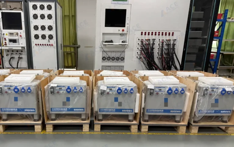
Assembled energy storage equipment units organized on a production rack before finished-unit aging test. The units had completed aluminum enclosure assembly and wiring connection before moving to the aging test process.
PCBA Assembly and Power-On Test
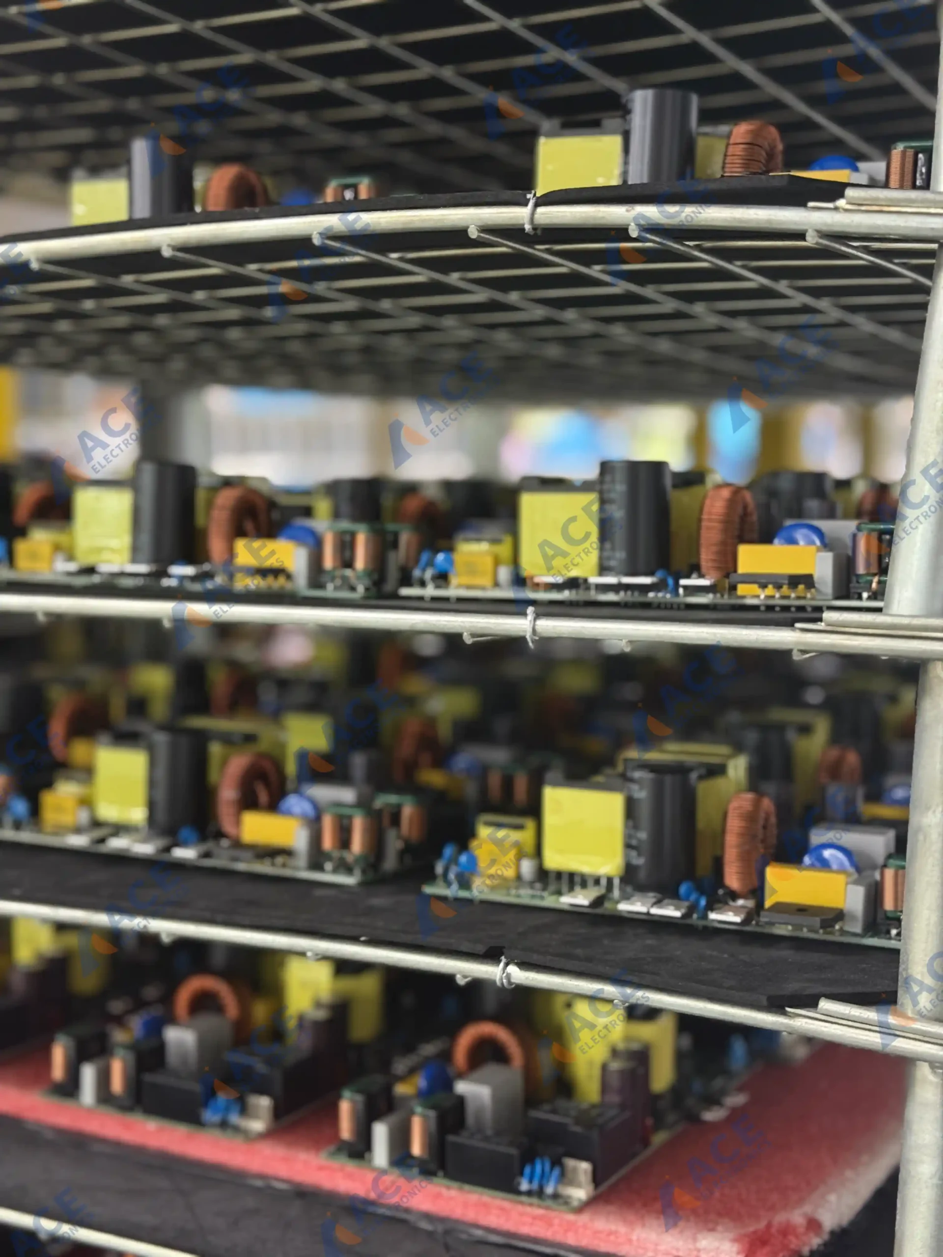
Power PCBA boards after SMT assembly and inline 3D AOI, staged before aluminum enclosure assembly.
The PCBs went through our PCBA assembly process: solder paste printing, pick-and-place, reflow, then wave soldering for through-hole parts like transformers and large connectors. All boards passed through inline 3D AOI during PCBA production — solder bridging, tombstoned components, missing parts, and insufficient wetting were caught automatically at this stage.
After PCBA assembly, each board went through an initial power-on test using a custom test fixture running the customer's own test program. The fixture applied 220V DC voltage power to the assembled PCB and verified that the main power rail was not shorted, all voltage rails came up within tolerance, and the board started without immediate faults.
Boards that passed this initial power-on test were cleared for the next step: final assembly into the customer-supplied aluminum enclosure with wiring harnesses and connectors. Boards that showed issues went back for diagnosis and rework.
Box Build Assembly: Enclosure, Wiring, and the First Problem We Hit
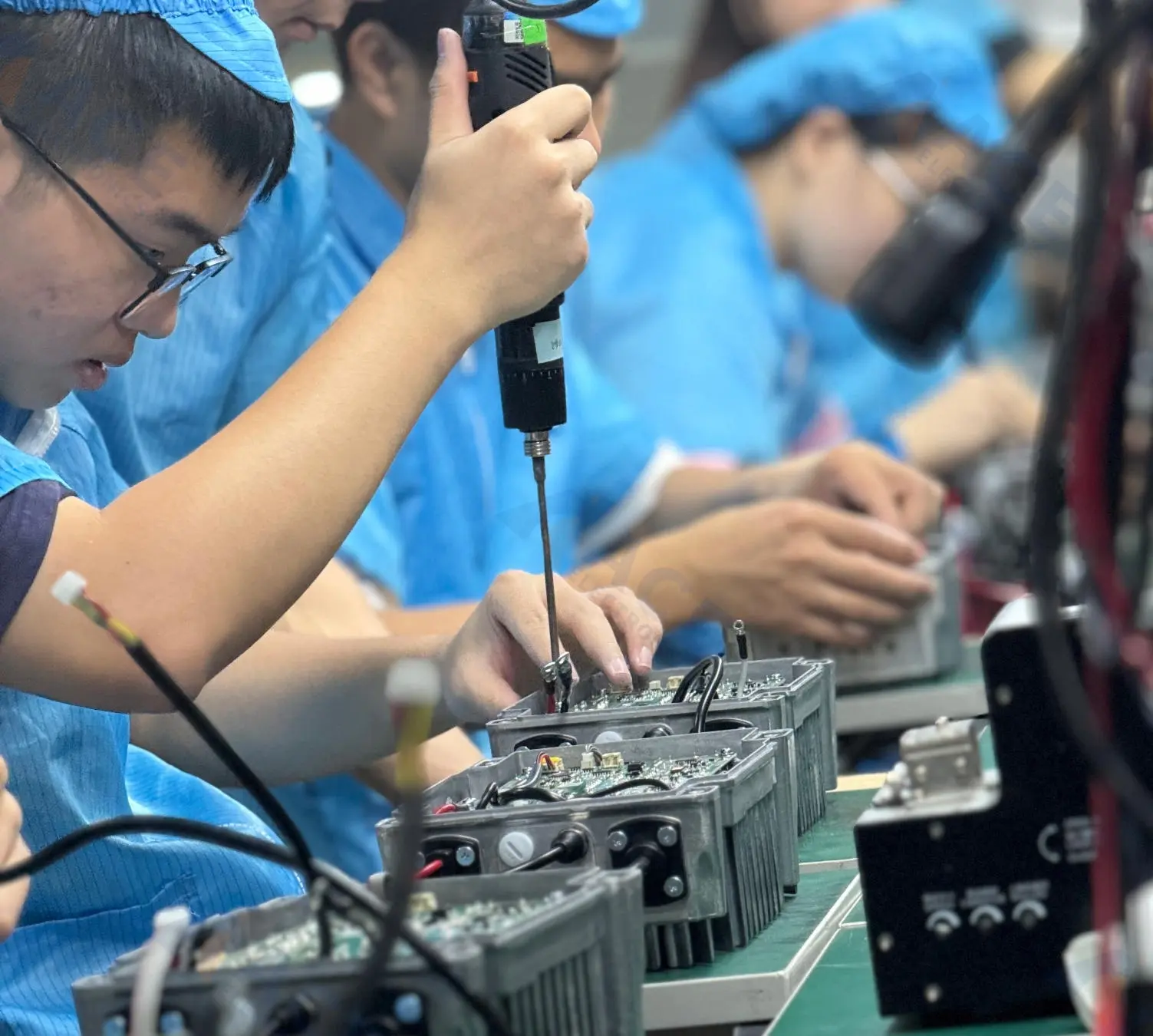
Operators assembling PCBA, wiring harnesses, connectors, and aluminum enclosures during the box build stage.
After the assembled PCB passed the power-on test, the box build assembly work started. Each unit went through these assembly steps:
- Place the PCBA into the aluminum enclosure at the designated mounting points
- Route the internal wiring harnesses through the defined paths inside the enclosure
- Mate each connector pair — board-side, harness-side, and panel-side
- Drive mounting screws for the PCBA, enclosure end panels, and structural brackets
- Align and close the enclosure panels
- Visual check before moving to aging test
The first problem: Enclosure tolerance on the pilot batch
On the first batch of roughly 30 units, we found that about 7 enclosures had slightly tight panel fit — the panels wouldn't close cleanly without force. The enclosures were within the customer's drawing tolerance, but at the tight end of the range, and the PCBA mounting bosses sat just high enough that the panel edges would catch.
We had two options:
- Force the panels closed (fast, but risked scratching the enclosure surface and stressing the PCBA)
- Flag the tight units for rework and feed the tolerance finding back to the customer for future enclosure batches (slower, but safer)
We chose the second option. For the defective enclosure, we returned them to client's cooperated aluminum enclosure factory for rework. We also informed the customer about the tolerance range we observed, and their subsequent enclosure batches arrived with a more consistent fit.
The second problem: Wiring harness routing interference
On the first ~20 units of the production run, about 4 units showed intermittent connector contact on one signal line during functional testing. The connector itself was fine. The wire was fine. The problem was routing: the harness was being bent too sharply around a mounting boss inside the enclosure, and under vibration the bent section was pulling slightly on the connector terminal.
After confirmation with clients, we adjusted the harness routing path to give the wires a wider bend radius around that mounting boss, added a small cable tie point on the assembly drawing, and reworked all the units that were assembled.
Functional Testing Before Aging
The test sequence on this project was: functional test first, then 24-hour aging test.
Our functional test for this project checked:
- Power-on sequence: correct startup behavior, no inrush anomalies
- Voltage rails: all rails present within tolerance
- Connector integrity: signals passing through every external connector
- Basic control functions: core operating modes working as specified
- Visual/auditory check: no unusual noise, no visible arcing, no hot-spot behavior
Here's what we recorded across the full 1000-unit run:
| Test stage | Units tested | Pass | Fail | Failure type | Action |
|---|---|---|---|---|---|
| Board-level power-on test | 1005 boards | 999 | 6 | Solder or component defects (caught after AOI clearance) | Reworked and retested |
| Functional test (finished unit) | 1005 units | 980 | 25 | Wiring routing (7), loose connector (10), enclosure fit (8) | Reworked and retested |
| Aging test (24h) | 1005 units | 1003 | 2 | intermittent connectors (2) | Diagnosed, reworked |
| Final inspection | 1005 units | 1003 | 2 | Enclosure surface scratches from handling | Touch-up, re-inspected |
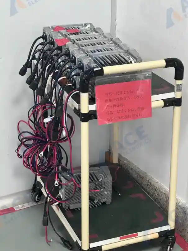
Energy storage equipment units placed on a transfer cart for production issue analysis before continuing through the assembly and testing process.
Finished-Unit Aging Test: 24-Hour Continuous Burn-In
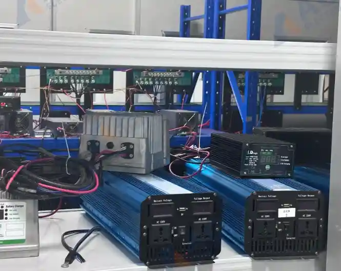
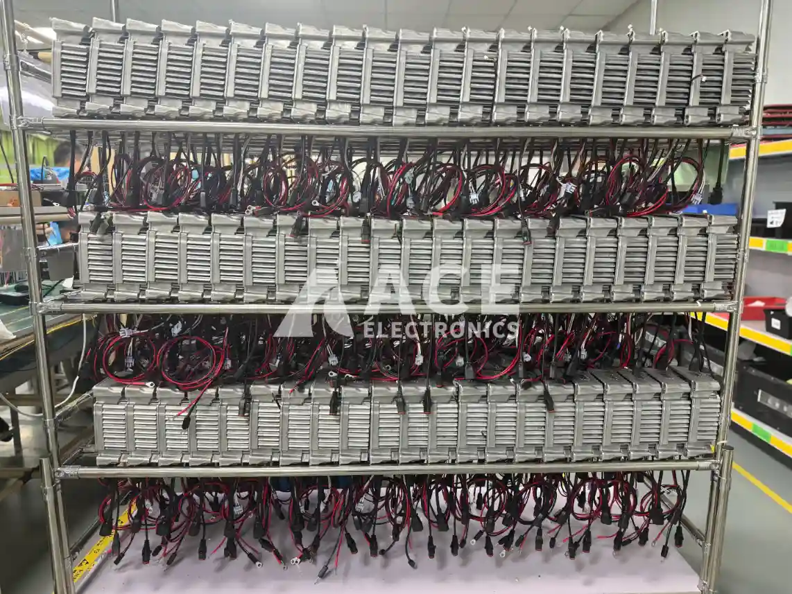
Finished small energy storage devices arranged for 24-hour batch aging test — after PCBA assembly, enclosure assembly, wiring, and functional testing.
The aging test was run on the finished units — after the PCBA, wiring harnesses, connectors, and aluminum enclosure were fully assembled and the unit had passed functional testing. The customer specified a 24-hour continuous burn-in.
Aging test setup
| Parameter | Detail |
|---|---|
| Batch size per cycle | 60 units per rack |
| Test condition | Finished unit, fully assembled, enclosure closed |
| Load type | Duty-cycle operation simulating field use |
| Monitoring | Individual power monitoring per unit |
| Duration | 24 hours continuous, per customer requirement |
| Check interval | Visual and data check every 8 hours |
| Pass criterion | Stable operation for full duration, no faults, no thermal anomalies |
Out of the 1005 units that entered aging, 2 showed issues:
- 2 units developed intermittent connector contact after several hours of thermal cycling. The connectors were re-seated and all three passed re-aging.
Final Inspection and Packaging
After the 24-hour aging cycle, all passing units went through final inspection:
| Check item | What we looked for | Results |
|---|---|---|
| Enclosure surface | Dents, scratches, handling marks | 2 units with minor scratches, reworked |
| Labels | Correct placement, legibility, spec match | All passed |
| External connectors | Clean, undamaged, properly seated | All passed |
| Panel screws | All present, tight, no cross-threading | All passed |
| Pre-pack condition | Unit clean and dry | All passed |
Packaging was anti-static bagging inside custom-cut foam inserts. The foam was designed to cradle each unit so the aluminum enclosure surface and protruding connectors absorbed no direct pressure from the outer carton. The cartons were labeled per the customer's shipping instructions.
![]()
An assembled energy storage device moved through the production line after aluminum enclosure assembly, wiring connection, and process identification.
Production Timeline
| Phase | Duration | Notes |
|---|---|---|
| Component sourcing and BOM review | ~2 weeks | Lead time driven by a few long-lead power semiconductors |
| PCB fabrication | ~1.5 weeks | Standard FR4 |
| PCBA assembly (all batches) | ~2 weeks | Run in batches with inline 3D AOI |
| Box build assembly and functional test | ~1 weeks | Includes rework cycles from pilot batch issues |
| Aging test (24h per batch) | ~1 weeks | Multiple aging rack cycles for 1000 units |
| Final inspection and packaging | ~1 days | Buffered by aging cycle completion |
| Total production | ~6 weeks | From BOM confirmation to shipment-ready |
Project Results
Based on our internal production records:
- ~1005 units manufactured through the full production flow
- Components sourced across the complete BOM, with no customer-side procurement
- ~1005 units shipped after final inspection and packaging
- Shipment delivered within the agreed production window
If you are preparing a production run for a power electronics or energy storage device and need a partner who can handle PCBA assembly, enclosure integration, wiring, functional testing, finished-unit aging, and packaging under one facility — send us your BOM and assembly drawings. We run a DFM review on every inquiry.
Have a project ready for manufacturing?
Fill out the form below and our engineering team will get back to you within 24 hours.