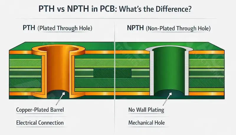
PTH (Plated Through Hole) has copper on the hole wall for electrical connection and soldering. NPTH (Non-Plated Through Hole) has no wall copper and is primarily used for mechanical, clearance, tooling, or alignment purposes, and its hole wall does not provide conductive connection.
Choose PTH when the hole must provide electrical continuity, connect copper layers, support a soldered component lead, or intentionally bond hardware to ground. Choose NPTH when the hole is used only for mechanical clearance, alignment, tooling, or isolated mounting with no intended conductive barrel connection.
This guide covers the manufacturing differences, design rules, and common DFM mistakes for both hole types.
What Are PTH and NPTH?
PTH (Plated Through Hole)
A PTH is a drilled hole whose wall is metallized through a chemical copper deposition step followed by copper electroplating. The resulting conductive barrel can connect copper layers, support through-hole solder joints, or provide an intentional electrical bond such as chassis ground.
Key characteristics:
- Wall material: Copper (electroless + electrolytic plating)
- Electrical function: Yes, when assigned to a conductive feature or net
- Size specification: Finished diameter (after plating)
- Typical specified hole-wall copper thickness is around 20 μm for IPC Class 2 and 25 μm for IPC Class 3, depending on the fabrication standard and reliability target.
Common applications:
- Through-hole component leads (resistors, capacitors, connectors)
- Vias and plated slots
- Grounded mounting holes (chassis ground, shielding)
- Test points
NPTH (Non-Plated Through Hole)
An NPTH is a drilled hole with no conductive copper plating on the hole wall. The barrel itself does not provide electrical connection, and the hole is typically used where electrical isolation or purely mechanical function is required.
Key characteristics:
- Wall material: Base laminate / substrate wall with no conductive barrel plating
- Electrical function: No conductive barrel connection
- Size basis: Often closer to the drilled size because there is no plating reduction in the hole barrel
- Tolerance: Depends on the fabricator, hole size, and drawing convention; do not assume NPTH is always tighter than PTH
Common applications:
- Screw and standoff clearance holes
- Tooling and alignment holes
- Mechanical location features
- Isolated mounting (no ground connection)
Quick Comparison
| Feature | PTH | NPTH |
|---|---|---|
| Wall structure | Metallized copper barrel | No conductive wall plating |
| Electrical role | Can provide electrical connection | No conductive barrel connection |
| Primary purpose | Electrical interconnect, soldering, sometimes grounded mounting | Mechanical clearance, tooling, alignment, isolated mounting |
| Hole size basis | Usually specified as finished hole size | Often closer to drilled size, depending on fab documentation |
| Tolerance | Varies by fabricator and finished-hole requirement | Varies by fabricator and hole type |
| Process flow | Drill, hole-wall preparation, chemical copper, copper plating, inspection | Non-plated drilling process, often handled separately in fabrication data |
| Relative cost | Usually higher due to metallization steps | May be lower, but not always, depending on fab flow and documentation |
When to Use PTH vs NPTH
Use PTH When:
- [ ] A through-hole component lead must be soldered into the hole
- [ ] The hole must provide electrical continuity between copper layers
- [ ] Mounting hardware needs chassis ground or shield connection
- [ ] The hole is part of a plated slot for grounding
Example: A terminal block pin hole is PTH because the lead must solder and carry current. For designs that rely on soldered lead insertion and stable barrel connection, our through-hole assembly service explains the practical requirements for THT assembly and plated-hole reliability.
Use NPTH When:
- [ ] The hole is used only for mechanical fastening, spacing, or support, with no intended conductive barrel function
- [ ] The hole serves tooling or alignment purposes
- [ ] No conductive connection through the hole barrel is allowed
- [ ] The feature is purely mechanical clearance
Example: An M3 corner mounting screw hole is often NPTH when the screw is used only for mechanical retention and no grounding or shielding connection is intended.
Critical Decision: Mounting Holes
Mounting holes cause the most PTH/NPTH confusion. Use this rule. For related mechanical-hole decisions, see our guide to counterbore vs. countersink holes in PCB.
| Hardware Type | Typical Choice | Reason |
|---|---|---|
| Plastic standoff | NPTH | No electrical contact needed |
| Metal screw + isolated board | NPTH | Prevent accidental grounding |
| Metal screw + chassis ground required | PTH | Intentional grounding path |
| Shield-can screw | PTH | EMI shielding connection |
DFM Case: A designer specified NPTH for a shield-can mounting hole, assuming that mounting holes should never be plated. As a result, the metal hardware was not reliably bonded to ground, which contributed to poor shielding performance during EMC testing. The fix was to change the hole to PTH and connect it properly to the ground structure.
Manufacturing Differences
1. Hole Size Specification
PTH: Usually specified by finished hole diameter, because copper plating reduces the final opening size. Additional process factors such as drill wear, desmear, and final finish may also affect the finished result.
A connector pin needs 1.00 mm clearance. If the expected plated wall thickness is about 25 μm per side, the drill size may need to be approximately 1.05 mm, subject to the fabricator’s process compensation.
Approximation:
Drill Size ≈ Target Finished Size + (2 × Expected Wall Plating Thickness) + Fabricator Compensation
NPTH: The final size is often closer to the drilled size because there is no conductive wall plating. However, the exact size convention still depends on the fabricator’s documentation rules and tolerance policy.
An M3 screw needs 3.2 mm clearance. The hole may be drilled near 3.2 mm, with the final size controlled according to the board shop’s mechanical drilling tolerance.
2. Process Flow
Typical PTH Manufacturing:
- Mechanical drilling
- Hole-wall cleaning / desmear
- Electroless copper deposition (seed layer)
- Electrolytic copper plating (build-up)
- Subsequent imaging / etching steps as required
Typical NPTH Manufacturing:
- Mechanical drilling in a non-plated drill stage
- Mechanical quality control such as burr control and dimensional verification
- No conductive wall metallization
Key difference: PTH adds hole-wall preparation and metallization steps that NPTH does not require. You can also review our PCB fabrication service for a broader look at bare-board process control, drill handling, and inspection capability.
3. Tolerance Control
| Aspect | PTH | NPTH |
|---|---|---|
| Diameter tolerance | Depends on finished-hole requirement and fabricator capability | Depends on hole size and fabricator capability |
| Primary variation source | Plating thickness, drill wear, process compensation | Drill accuracy, wear, burrs, positioning |
| Location tolerance | Depends on board shop capability and drawing requirement | Depends on board shop capability and drawing requirement |
| Aspect ratio concern | Important for plating uniformity and reliability | Less affected by plating, but drilling quality still matters in thick boards |
Note: High aspect ratio PTHs are harder to plate uniformly and may create higher reliability risk in thick boards with small holes.
4. Quality Inspection
PTH inspection points:
- Hole-wall copper thickness
- Plating voids or insufficient coverage
- Barrel or corner cracking under thermal stress
- Registration and internal layer connection quality
NPTH inspection points:
- Diameter accuracy
- Position relative to copper features
- Burr removal quality
- Edge distance and breakout risk
Design and DFM Guidelines
Drill File Preparation
Best practice: Provide separate drill files for plated and non-plated holes whenever possible.
| File | Content | Naming Example |
|---|---|---|
| Plated drill | All PTH, vias, plated slots | pcbname_pth.drl |
| Non-plated drill | All NPTH, tooling holes | pcbname_npth.drl |
Why separate files: Separate drill outputs reduce ambiguity and help CAM engineers avoid inferring intent from pads, copper clearance, or layer count. If your production package still depends on CAM interpretation, a formal PCB DFM review can catch drill-file and fabrication-note issues before release.
Common Design Mistakes
Mistake 1: Confusing Drill Size with Finished Size
Error: Specifying a 1.00 mm drill when the design actually requires a 1.00 mm finished plated hole.
Result: After hole-wall plating and process variation, the finished hole can be smaller than required, so the pin may not fit properly.
Fix: Specify the required finished hole size for PTH features and let the fabricator determine the drill size based on its plating process and tolerance rules.
Mistake 2: Insufficient Copper Clearance Around NPTH
Error: NPTH placed too close to copper traces or planes.
Risk: If an NPTH is too close to copper, drilling tolerances, burrs, or breakout can damage nearby copper features or reduce isolation margin.
Guideline: Keep adequate copper clearance around NPTH features according to the fabricator’s design rules. As a practical shop-floor rule, some manufacturers recommend about 0.30 mm minimum drill-to-copper clearance, with larger margins preferred in high-reliability designs.
Mistake 3: Wrong Mounting Hole Type
Error: All mounting holes default to NPTH without checking grounding requirements.
Risk: Floating metal hardware, degraded shielding performance, unintended grounding behavior, or grounding function not working as intended.
Fix: Review every mounting hole's electrical intent. Mark grounded holes clearly in fabrication notes.
Mistake 4: Ambiguous Plated Slot Callouts
Error: Slot shown in mechanical layer without specifying plated or non-plated.
Risk: If the slot is not clearly identified, the CAM engineer may need to infer intent or raise a query, which can cause delay or incorrect interpretation.
Fix: Explicitly label "PLATED SLOT" or "NON-PLATED SLOT" in drill file and fabrication drawing.
Fabrication Documentation Checklist
Include in your fab notes:
- [ ] Separate PTH and NPTH drill files (or clear layer coding)
- [ ] Required finished hole sizes for plated holes where fit or assembly is critical
- [ ] Clearly defined NPTH hole sizes according to the fabricator’s preferred documentation method
- [ ] Plated slot callouts with dimensions
- [ ] Mounting hole grounding intent (which holes tie to ground)
- [ ] Special tolerance requirements (if any)
- [ ] Hole-to-edge minimum distances
Reliability and Cost Considerations
PTH Reliability Risks
Barrel cracking: Thermal cycling stress can crack the copper barrel, especially in high aspect ratio holes.
Plating voids: Incomplete copper coverage creates weak points.
Z-axis expansion: CTE mismatch between copper and FR4 causes stress at hole corners.
Mitigation:
- Keep aspect ratio within the fabricator’s reliable plating capability
- Specify the required minimum hole-wall copper thickness based on the product class
- Avoid unnecessarily small drilled holes in thick boards, and consult the fabricator for high-aspect-ratio or high-reliability designs
NPTH Reliability Risks
Copper breakout: If the hole is too close to copper, drilling variation can break into a trace or plane.
Burr-related contact: Poor hole quality can leave burrs or reduce insulation margin near adjacent copper features.
Misalignment: Tight-tolerance NPTH features can create assembly or mechanical fit problems if the hole position drifts.
Cost Impact
| Factor | PTH | NPTH |
|---|---|---|
| Process complexity | Higher due to hole-wall preparation and metallization | Lower because no conductive barrel plating is required |
| Inspection focus | More emphasis on metallization quality and hole reliability | More emphasis on mechanical accuracy, burr control, and clearance |
| Main yield risk | Plating-related defects | Mechanical tolerance, breakout, or interpretation errors |
| Tight-tolerance impact | Can add cost significantly, depending on hole size and reliability class | Can also add cost significantly, depending on mechanical precision requirements |
Rule: Do not choose NPTH solely to reduce cost. Choose the hole type by function. Using NPTH where a conductive or grounded hole is required can create failures that are far more expensive than the added plating process.
PTH vs NPTH Quick Reference
| Decision Point | Choose PTH | Choose NPTH |
|---|---|---|
| Component lead soldering | ✓ | ✗ |
| Layer-to-layer electrical connection | ✓ | ✗ |
| Chassis ground or shielding connection | ✓ | ✗ |
| Pure mechanical mounting with no intended grounding | ✗ | ✓ |
| Electrical isolation required | ✗ | ✓ |
| Tooling or alignment only | ✗ | ✓ |
Need DFM review? If you want a second check on your Gerber package, drill files, and fabrication notes, see our PCB layout support and DFM review service.
+++FAQ+++
Is every through hole plated?
No. "Through hole" describes geometry (hole passes through board). It can be plated (PTH) or non-plated (NPTH).
Are mounting holes always NPTH?
No. Many are NPTH, but mounting holes can be PTH when the hardware must connect to ground or shielding.
Why specify finished size for PTH?
Copper plating reduces the final internal diameter, so plated holes are usually specified by required finished size rather than raw drill size.
Can NPTH connect to a circuit?
Not through the hole wall. If conductive barrel connection is required, use PTH; if only surface contact is needed, define that separately in the pad/copper design.
Do all through-hole components need PTH?
For standard electrical through-hole components, yes. Soldered leads and press-fit leads normally require a properly designed plated hole to provide reliable mechanical and electrical contact. Non-electrical locating or mechanical features are a different case.
Why separate PTH and NPTH drill files?
Clarity. Separate drill files reduce CAM interpretation, prevent ambiguity between conductive and non-conductive holes, and lower the risk of manufacturing errors.
Is NPTH always cheaper?
Usually, but tight tolerances or difficult positioning can add cost. Function should drive the choice, not cost alone.
What is the most common PTH design error?
Specifying drill diameter instead of finished plated diameter, causing component fit failures.
+++FAQ+++
Related Reading
- Counterbore vs. Countersink Holes in PCB: Which One is Right for Your Design?
- PCB Layout Support & DFM for PCBA
- PCB Fabrication Service
- Through-Hole (THT) PCB Assembly Factory
- How to Choose PCB Surface Finish
About the Author
Bill Ho is Sales Engineer and Chief Editor at ACE Electronics, with 10 years of experience in PCB fabrication and PCB assembly.
He writes practical technical content focused on manufacturability review, fabrication communication, and assembly risk reduction.