Circuit board components are the electronic and electromechanical parts mounted on a printed circuit board to create a working circuit. Common examples include resistors, capacitors, inductors, diodes, transistors, ICs, connectors, sensors, relays, fuses, switches, oscillators, and protection devices.
For buyers, hardware teams, and purchasing teams, the BOM should make each component clear enough to source and place. At minimum, confirm the function, package, key ratings, and manufacturer part number. For critical, long-lead, or substitute parts, also check lifecycle status and approved sourcing options.
What Are Circuit Board Components?
Circuit board components are the functional parts placed on a PCB. In this guide, PCB components and circuit board components refer to the same practical idea: the parts listed in the BOM and mounted on the board during assembly.
Component information usually appears in the BOM, datasheets, PCB footprint names, reference designators, and package descriptions. For sourcing and approved-alternative review, the most important details are the manufacturer part number, electrical rating, package, footprint, lifecycle status, and any substitution restrictions.
Common Circuit Board Components and Their Functions
Most circuit boards use a mix of passive components, active semiconductors, connectors, timing parts, protection devices, and electromechanical parts.
| Component | Typical Reference Designator | What It Does | Main Types | Key Selection Parameters |
|---|---|---|---|---|
| Resistor | R | Limits current, divides voltage, sets bias points | Fixed, current sense, resistor array, trimmer | Resistance, tolerance, power rating, TCR, package |
| Capacitor | C | Stores charge, filters noise, stabilizes voltage | MLCC, electrolytic, tantalum, polymer, film | Capacitance, voltage, ESR, dielectric, ripple current, polarity |
| Inductor | L | Stores energy, filters current, supports power conversion | Power inductor, RF inductor, coupled inductor | Inductance, rated current, saturation current, DCR, shielding |
| Ferrite bead | FB or L | Suppresses high-frequency noise | Chip ferrite bead, common-mode choke | Impedance curve, rated current, DCR, frequency behavior |
| Diode | D | Allows current in one direction or protects a circuit | Signal, rectifier, Schottky, Zener, TVS | Forward voltage, reverse voltage, current, recovery time, capacitance |
| LED | D or LED | Emits light for indication or sensing | Standard LED, RGB LED, infrared LED | Color, current, brightness, viewing angle, polarity, package |
| Transistor | Q | Switches or amplifies signals | BJT, MOSFET, IGBT | Voltage, current, gain or RDS(on), gate charge, package, thermal rating |
| Integrated circuit | U or IC | Performs logic, control, regulation, memory, or signal processing | MCU, regulator, op amp, memory, driver, RF IC | Function, package, voltage, interface, lifecycle, firmware/test needs |
| Connector | J, CN, P | Connects the PCB to cables, power, other boards, or interfaces | Board-to-board, wire-to-board, FPC, terminal block | Pitch, pin count, current, voltage, orientation, mating part |
| Crystal or oscillator | Y, X, OSC | Provides timing reference | Crystal, resonator, oscillator module | Frequency, tolerance, stability, load capacitance, package |
| Relay | K, RL | Switches isolated or higher-power circuits | Signal relay, power relay, solid-state relay | Coil voltage, contact rating, footprint, height, isolation |
| Switch | SW | Provides manual or configuration input | Tactile, slide, DIP, rotary | Current, height, actuator, lifecycle, mounting style |
| Fuse | F | Protects against overcurrent | One-time fuse, resettable fuse, PTC | Current rating, voltage rating, trip behavior, package |
| Sensor | U, S, SEN | Detects physical inputs | Temperature, pressure, motion, light, current | Range, accuracy, interface, calibration, exposure, package |
| Transformer | T | Transfers or isolates energy | Power, pulse, signal, isolation transformer | Turns ratio, current, isolation, frequency, size, safety spacing |
| Potentiometer | RV, VR, R | Provides adjustable resistance | Trimmer, rotary potentiometer | Resistance, taper, adjustment style, lifecycle, package |
Resistors
Resistance is a measure of the opposition to current flow in an electrical circuit.
Resistors limit current and help set voltage levels in a circuit. They are used for current limiting, voltage division, biasing, pull-up and pull-down resistor circuits, signal conditioning, current sensing, and feedback circuits.
Resistors are available in a wide range of values, from milliohms to megohms. Standard resistors commonly have tolerances of 1% to 5%, while precision resistors can offer much tighter tolerances, such as 0.1%, 0.01%, or even 0.001%. These precision parts are more expensive and are often used in analog circuits, sensing circuits, and reference-voltage circuits where accuracy is important.
Resistors also come in different power ratings, such as 1/8 W, 1/4 W, 1/2 W, 1 W, and 5 W. SMD resistors are available in common package sizes such as 1210, 1206, 0805, 0603, 0402, and 0201. Smaller packages save PCB space, while larger packages usually support higher power dissipation. Resistor arrays, also called resistor networks or R-packs, integrate multiple resistors into one package and are often used for pull-up or pull-down circuits and compact PCB layouts.
Common Resistor Types
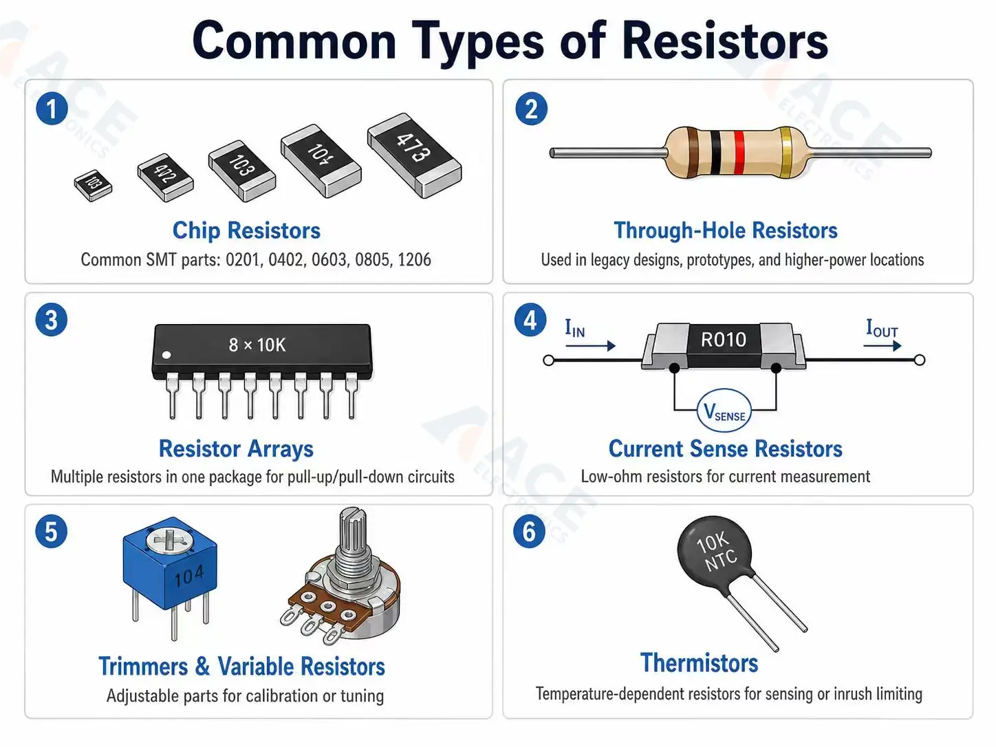
Common resistor types include:
- Chip resistors: the most common SMT resistors, available in sizes such as 0201, 0402, 0603, 0805, and 1206.
- Through-hole resistors: often used in legacy designs, prototypes, higher-power locations, or serviceable products.
- Resistor arrays: multiple resistors integrated into a single package, often used for pull-up/pull-down circuits or space-saving PCB layouts.
- Current sense resistors: low-ohm resistors used to measure current in power and battery circuits.
- Trimmers and variable resistors: adjustable parts used for calibration or tuning.
- Thermistors: temperature-dependent resistors used for sensing or inrush-current limiting.
Common resistor types should be selected by resistance value, tolerance, power rating, package size, current sensing needs, and adjustment requirements.
Common Resistor Materials
| Type | Characteristics | Typical Applications |
|---|---|---|
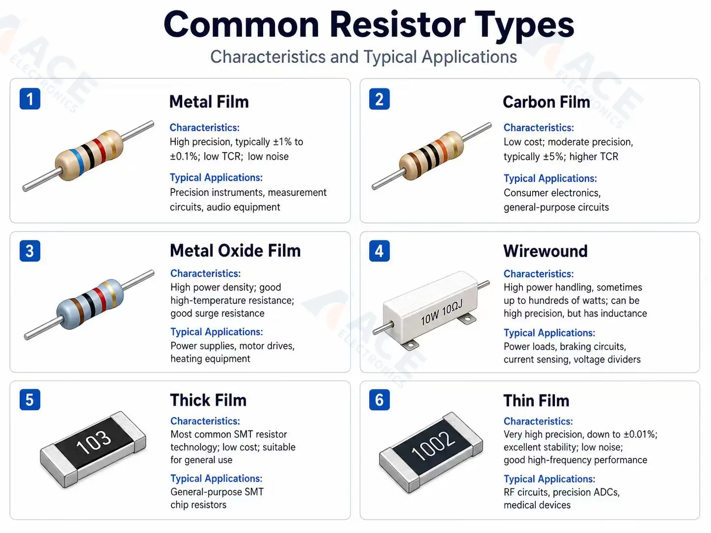
| Metal film | High precision, typically ±1% to ±0.1%; low TCR; low noise | Precision instruments, measurement circuits, audio equipment |
| Carbon film | Low cost; moderate precision, typically ±5%; higher TCR | Consumer electronics, general-purpose circuits |
| Metal oxide film | High power density; good high-temperature resistance; good surge resistance | Power supplies, motor drives, heating equipment |
| Wirewound | High power handling, sometimes up to hundreds of watts; can be high precision, but has inductance | Power loads, braking circuits, current sensing, voltage dividers |
| Thick film | Most common SMT resistor technology; low cost; suitable for general use | General-purpose SMT chip resistors |
| Thin film | Very high precision, down to ±0.01%; excellent stability; low noise; good high-frequency performance | RF circuits, precision ADCs, medical devices |
Resistor material affects tolerance, temperature coefficient, noise, stability, power handling, and sourcing options.
Resistor Selection Parameters
| Parameter | What to Check | Why It Matters |
|---|---|---|
| Resistance value | Required ohm value, such as 10 Ω, 1 kΩ, or 100 kΩ | Determines current limiting, voltage division, biasing, or feedback behavior |
| Tolerance | Common values include ±5%, ±1%, ±0.1%, or tighter | Affects circuit accuracy. Precision applications need tighter tolerance |
| Power rating | Common ratings include 1/16 W, 1/10 W, 1/8 W, 1/4 W, 1/2 W, or higher | Prevents overheating by ensuring the resistor can handle the required power dissipation |
| Temperature coefficient | Usually specified in ppm/°C | Shows how much the resistance value changes when temperature changes |
| Package size | Common SMD sizes include 0201, 0402, 0603, 0805, 1206, and 1210 | Affects PCB space, assembly difficulty, power handling, and sourcing availability |
| Voltage rating | Maximum working voltage across the resistor | Important for high-voltage dividers, sensing circuits, and voltage monitoring |
| Operating temperature range | Example: -55°C to +125°C, depending on resistor type | Ensures reliable operation under real product conditions, including environmental heat and self-heating |
| Qualification / reliability grade | AEC-Q200, automotive grade, sulfur-resistant, anti-surge, or other special ratings | Required for automotive, industrial, outdoor, or long-life products that face harsher operating conditions |
Sourcing and Package Notes
Resistors are usually easy to source, but not every resistor is interchangeable. Precision resistors, current sense resistors, high-voltage resistors, and resistor arrays need closer review. A current sense resistor with the same resistance value may still differ in power rating, TCR, package, and thermal behavior.
For very small packages such as 0201 or 0402, package selection can affect placement capability, inspection, and approved-alternative availability. If an alternate is proposed, check resistance, tolerance, power rating, package, temperature coefficient, and lifecycle status.
Examples of common international resistor manufacturers include Yageo, Kemet, Vishay, Panasonic, KOA Speer, Stackpole, Bourns, Murata and Rohm.
Capacitors
Capacitors store electrical charge and release it when needed. On PCBs, they are used for decoupling, filtering, smoothing, coupling, timing, energy storage, and voltage stabilization.
Common Capacitor Types
Common capacitor types include:
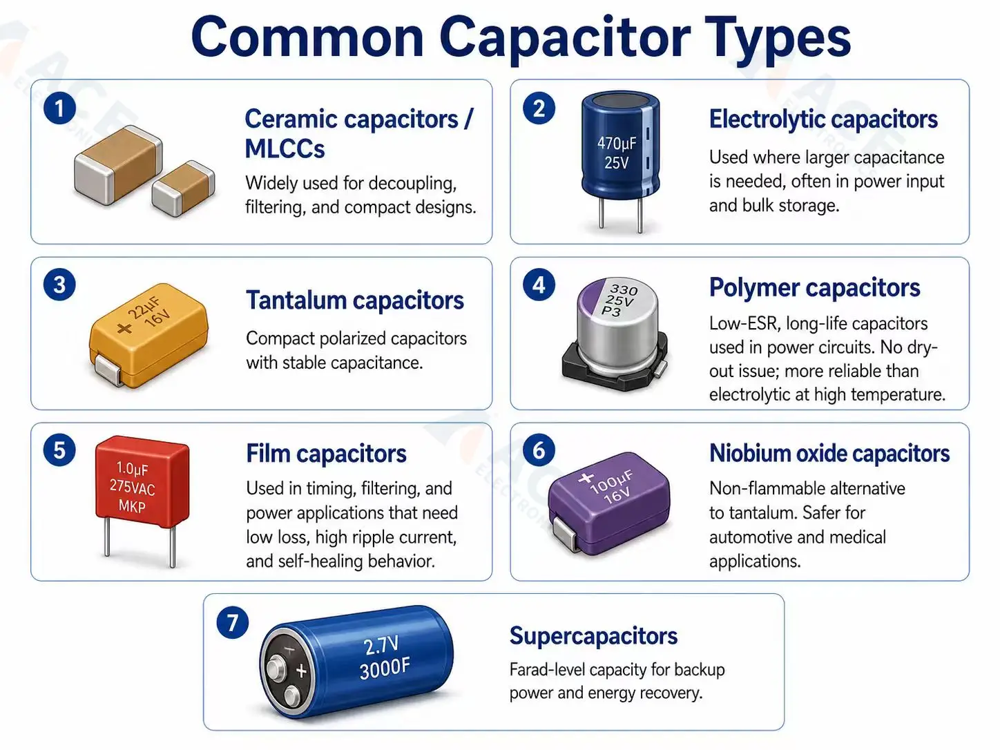
- Ceramic capacitors / MLCCs: widely used for decoupling, filtering, and compact designs. Caution: capacitance drops significantly under DC bias; check manufacturer curves.
- Electrolytic capacitors: used where larger capacitance is needed, often in power input and bulk storage. Caution: lifetime is temperature-dependent; derate for long-life designs.
- Tantalum capacitors: compact polarized capacitors with stable capacitance. Caution: must be voltage-derated ≥50% (MnO₂ type); supply chain and price volatility are ongoing risks.
- Polymer capacitors: low-ESR, long-life capacitors used in power circuits. No dry-out issue; more reliable than electrolytic at high temperature.
- Film capacitors: used in timing, filtering, and power applications that need low loss, high ripple current, and self-healing behavior.
- Niobium oxide capacitors: non-flammable alternative to tantalum. Safer for automotive and medical applications.
- Supercapacitors: farad-level capacity for backup power and energy recovery.
Common capacitor types differ in capacitance range, voltage rating, ESR, polarity, package size, and sourcing availability.
Capacitor Selection Parameters
| Parameter | What to Check | Why It Matters |
|---|---|---|
| Capacitance | Nominal value (μF, nF, or pF); verify actual value in precision circuits | Sets filtering, storage, coupling, or timing behavior |
| Voltage rating | Rated voltage should exceed operating voltage with margin (e.g., 25–50%) | Prevents breakdown under operating conditions |
| Tolerance | Typical ±10%, ±5%, ±1%, or tighter; select based on application precision | Affects timing, filtering, and analog performance |
| Temperature characteristic | Verify dielectric type: X7R, X5R, Y5V, C0G/NP0; consider ±%/°C drift | Incorrect class may cause capacitance drift with temperature |
| Grade / qualification | Check grade: AEC-Q200 (automotive), industrial, medical, or military | Higher grade ensures tighter testing, longer life, fewer failures |
| Dielectric | Check type: ceramic, film, tantalum, electrolytic; verify stability, voltage, and cost | Changes stability, size, cost, and voltage behavior |
| ESR | Verify ESR (mΩ–Ω); lower ESR preferred for high-frequency decoupling | Important in power filtering and ripple performance |
| ESL | Check datasheet for nH; smaller packages usually have lower ESL | Limits high-frequency decoupling |
| Ripple current | Check maximum AC/RMS ripple current for electrolytic, polymer, or film capacitors | Prevents overheating and ensures reliability |
| DC bias effect | Verify capacitance at operating DC voltage; consult derating curves | MLCC capacitance collapses under DC voltage |
| Polarity | Confirm correct orientation for electrolytic or tantalum | Incorrect orientation may cause capacitor failure or damage |
| Package and height | Ensure package fits PCB footprint and enclosure; affects placement and clearance | Affects placement, board fit, and thermal performance |
| Temperature and lifetime | Verify operating temperature range and expected lifetime (MTBF) | Critical for power, industrial, or high-temperature products |
| Aging / derating | Check expected capacitance decay over time; derate tantalum voltage as needed | Ensures long-term performance and reliability |
Common Selection Pitfalls
| Pitfall | What Happens | How to Avoid |
|---|---|---|
| Ignoring MLCC DC bias | Effective capacitance drops 60–80% under load | Check manufacturer DC bias curves at operating voltage |
| Under-derating tantalum | Short circuit → thermal runaway → fire (MnO₂) | Derate MnO₂ tantalum to ≤50% rated voltage; consider polymer or niobium oxide |
| Ignoring electrolytic lifetime | Capacitor dries out, ESR rises, power supply fails | Use 105°C-rated parts, add thermal margin, or switch to polymer |
| Large MLCC near stress points | Mechanical flex → ceramic cracking → short | Use soft-termination MLCCs or polymer capacitors in flex-prone areas |
Polarity, ESR, and DC Bias
Capacitors look simple in a BOM, but they are one of the easiest categories to under-specify. MLCCs can lose effective capacitance under DC bias. Electrolytic capacitors have lifetime limits that depend on temperature and ripple current. Tantalum capacitors need careful voltage derating and polarity control.
ESR affects filtering and power stability. Very low ESR can be helpful in switching regulator circuits, but the regulator datasheet should be checked because some circuits require a specific output capacitor type or ESR range.
Sourcing and Assembly Notes
Capacitor alternates should be checked for capacitance, voltage, tolerance, dielectric, ESR, package, height, polarity, temperature rating, and lifecycle status. A package change from 0603 to 0402 or from one electrolytic diameter to another can create footprint or enclosure issues.
Examples of common capacitor manufacturers include Murata, TDK, Samsung Electro-Mechanics, KYOCERA AVX, KEMET, Panasonic, Nichicon, Rubycon, and Vishay.
Inductors and Ferrite Beads
Inductors store energy in a magnetic field and resist changes in current. They are common in switching power supplies, RF circuits, filters, and EMI control. Ferrite beads are related parts used mainly to suppress high-frequency noise.
Inductors vs Ferrite Beads
An inductor is usually selected for energy storage, filtering, or impedance in a defined circuit. A ferrite bead is usually selected for high-frequency noise suppression. They may look similar in a BOM, but they are not direct substitutes.
| Feature | Inductor | Ferrite Bead |
|---|---|---|
| Main use | Store energy, smooth current, help power conversion | Block high-frequency noise on power/signal lines |
| Key point | Rated current, size, type (toroid, chip, etc.) | Works at target frequency, rated current |
| Behavior / Risk | Can overload if current too high → circuit issues | Can lose effectiveness if wrong type/frequency chosen |
| Common location | Power supplies, filters | Power rails, data/signal lines |
| Replacement risk | Wrong type → ripple, efficiency loss | Wrong type/frequency → noise not suppressed |
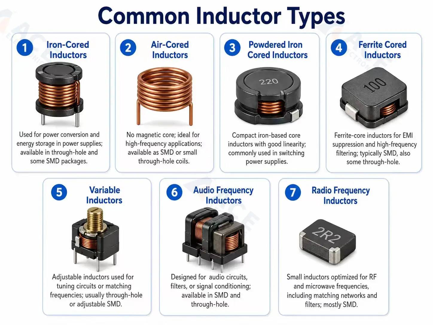
Common Types
- Iron-cored inductors: inductors with iron cores, typically used for power conversion or energy storage in power supplies; available in through-hole and some SMD packages.
- Air-cored inductors: inductors without a magnetic core, ideal for high-frequency applications; usually available as SMD or small through-hole coils.
- Powdered iron cored inductors: compact iron-based core inductors with good linearity, commonly used in switching power supplies; available in SMD and through-hole.
- Ferrite cored inductors: inductors with ferrite cores for EMI suppression and high-frequency filtering; typically SMD, also some through-hole.
- Variable inductors: adjustable inductors used for tuning circuits or matching frequencies; usually through-hole or adjustable SMD.
- Audio frequency inductors: designed for audio circuits, filters, or signal conditioning; available in SMD and through-hole.
- Radio frequency inductors: small inductors optimized for RF/microwave frequencies, including matching networks and filters; mostly SMD.
Inductors and ferrite beads are selected by inductance or impedance curve, current rating, saturation current, DCR, shielding, and package size.
Inductor Selection Parameters
| Parameter | What to Check | Why It Matters |
|---|---|---|
| Inductance | Nominal value in μH; check typical range for the application | Determines filtering, energy storage, and ripple smoothing |
| Rated current | Maximum continuous current the inductor can handle | Prevents overheating or failure under normal load |
| Saturation current | Current at which inductance drops significantly | Ensures stable performance under peak load conditions |
| DCR (DC resistance) | Measure in ohms; lower DCR preferred for power efficiency | Affects power loss, heat generation, and overall efficiency |
| Shielding | Whether inductor has magnetic shielding or unshielded | Reduces EMI and unwanted coupling to nearby components |
| Self-resonant frequency | Frequency at which inductor starts acting as a capacitor | Important for high-frequency/RF circuits to avoid performance drop |
| Package & height | Check SMD/through-hole type, footprint, and height for PCB fit | Ensures mechanical fit, manufacturability, and sourcing compatibility |
Sourcing and Assembly Notes
Power inductors can be large, height-sensitive, and harder to substitute than they appear. A replacement inductor with the same inductance may have different saturation current, DCR, shielding, and thermal behavior.
Ferrite beads should be reviewed against impedance curves, not just part numbers or package size. In EMI-sensitive products, changing a bead or inductor can change test results.
Examples of common inductor and ferrite manufacturers include TDK, Murata, Bourns, Würth Elektronik, Coilcraft, Taiyo Yuden, and Vishay.
Diodes and LEDs
Diodes control current direction or protect a circuit from unwanted voltage conditions. LEDs are diodes that emit light and are used for indication, optical output, sensing, and user-interface feedback.
Common Diode Types
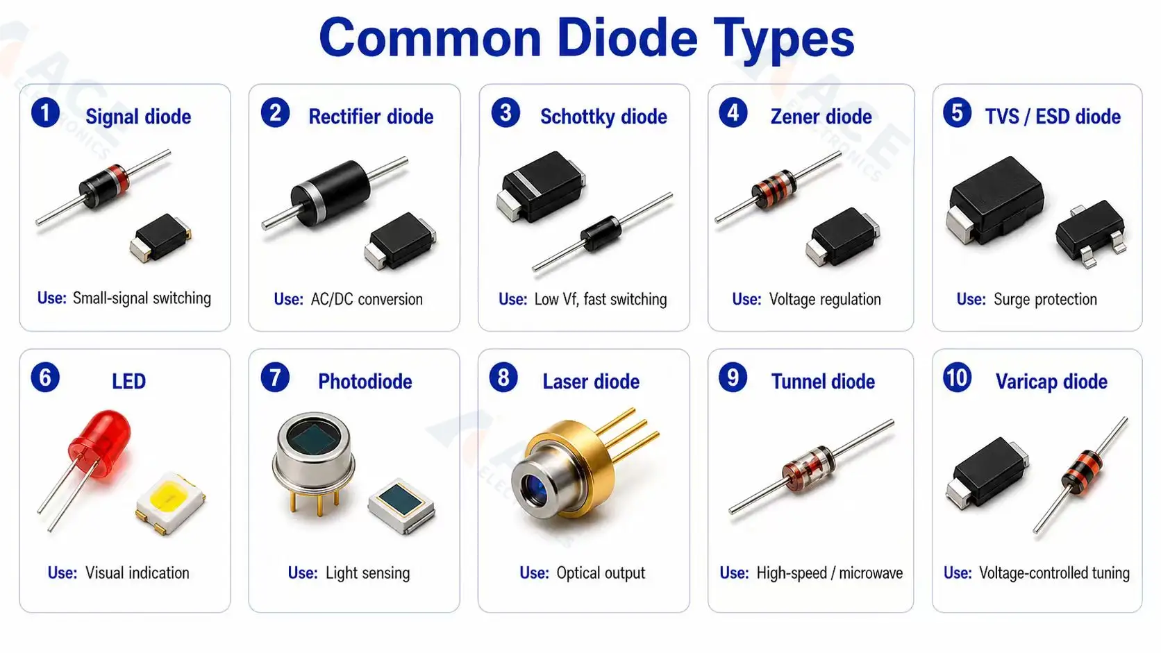
| Type | Typical Use | Selection Notes |
|---|---|---|
| Signal diode | Small-signal switching, logic circuits | Check speed, current, voltage, package |
| Rectifier diode | AC/DC conversion, power paths | Check current rating, reverse voltage, package, heat dissipation |
| Schottky diode | Fast switching, low forward voltage | Check leakage, current, voltage, thermal rating |
| Zener diode | Voltage regulation or reference | Check Zener voltage, power rating, tolerance, current |
| TVS / ESD diode | Surge and static protection | Check working voltage, clamping voltage, capacitance, package |
| LED | Visual indicator or optical signal | Check color, current, brightness, viewing angle, polarity, height |
| Photodiode | Light detection and sensing | Check wavelength, current, reverse voltage, package |
| Laser diode | Optical communication or laser output | Check wavelength, current, power, polarity, package |
| Tunnel diode | High-speed switching, microwave circuits | Specialty item; check voltage, current, package |
| Varicap diode | Voltage-controlled tuning | Specialty item; check capacitance range, voltage, package |
Diode selection depends on current direction, voltage rating, forward voltage, recovery behavior, protection needs, and polarity marking.
Diode Selection Parameters
| Parameter | What to Check | Why It Matters |
|---|---|---|
| Diode type | Signal, rectifier, Schottky, Zener, TVS, LED, or photodiode | Different diode types are designed for different functions and should not be replaced only by package size |
| Reverse voltage rating | Maximum reverse voltage or working voltage | Prevents breakdown when the diode is reverse-biased |
| Forward current rating | Continuous current and peak current ratings | Ensures the diode can handle the required current safely |
| Forward voltage | VF at the specified current | Affects voltage drop, power loss, and heat |
| Power and thermal rating | Power dissipation, thermal resistance, and package | Prevents overheating during operation |
| Package size | SMD or through-hole package, footprint, and height | Affects PCB layout, assembly, heat dissipation, and sourcing |
| Switching speed | Reverse recovery time for switching or rectifier diodes | Important in fast switching circuits and power supplies |
| Leakage current | Reverse leakage current | Important for low-power, battery, and sensing circuits |
| Capacitance | Junction capacitance, especially for TVS and signal diodes | Low capacitance is needed for high-speed signal lines |
| Protection rating | Surge current, clamping voltage, and peak pulse power for TVS diodes | Ensures the protection diode can handle ESD or surge events |
| LED parameters | Color, brightness, viewing angle, current, polarity, and height | Ensures the LED meets visual and mechanical requirements |
| Qualification / reliability grade | AEC-Q101, automotive grade, or other reliability requirements | Required for automotive, industrial, outdoor, or long-life products |
Polarity and Package Notes
Diodes and LEDs are polarity-sensitive. The PCB silkscreen, assembly drawing, and component datasheet should make orientation clear. LED lens height, light direction, color, brightness, and enclosure window alignment can also matter.
Examples of common diode and LED manufacturers include Vishay, onsemi, Nexperia, Diodes Incorporated, STMicroelectronics, Rohm, Lite-On, Kingbright, and Everlight.
Transistors, MOSFETs, and Power Devices
Transistors switch or amplify electrical signals. MOSFETs are widely used in power switching, load control, battery circuits, motor control, and level shifting. BJTs are still used in many signal and switching applications.
Common Transistor and Power Device Types
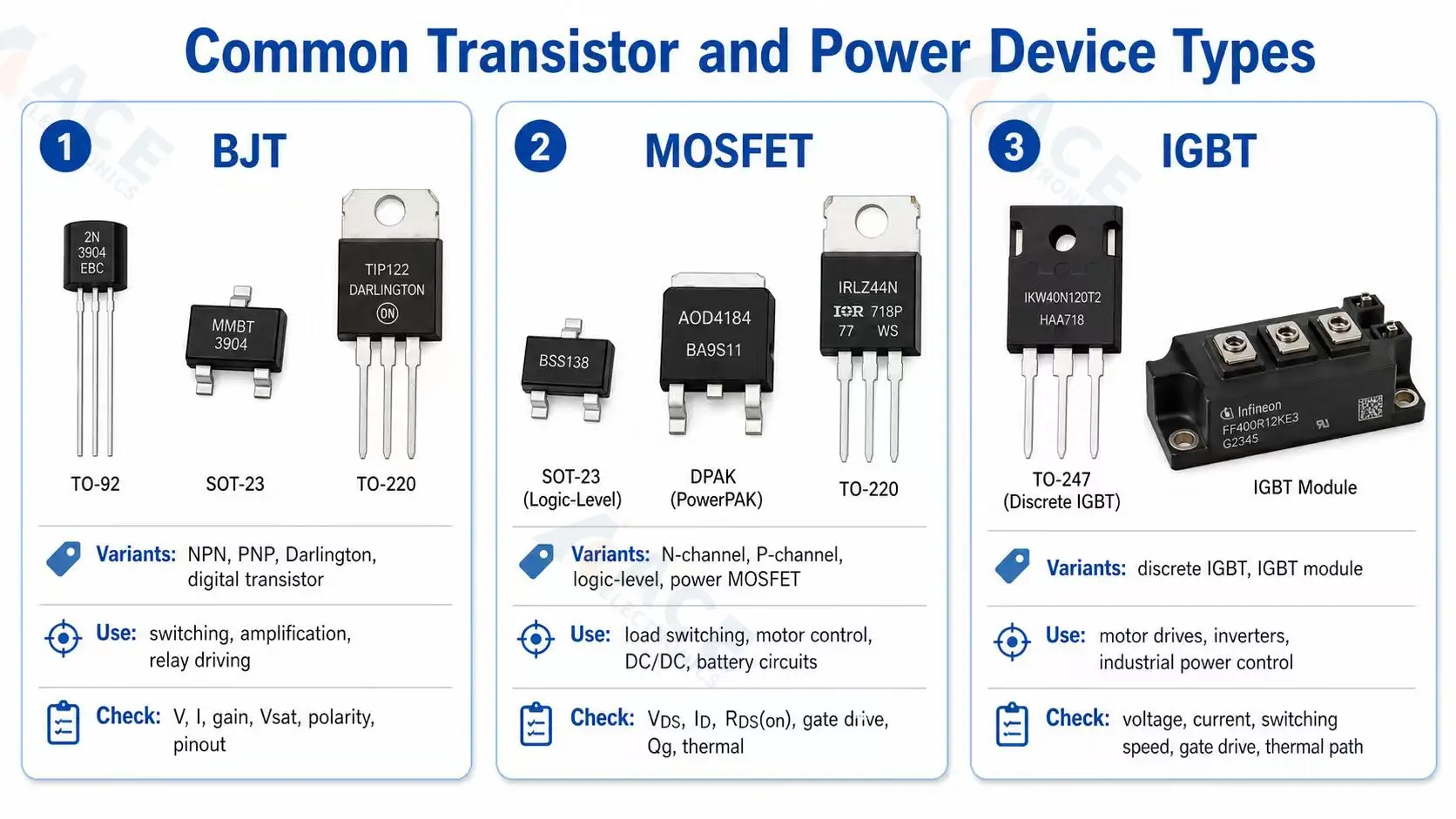
| Device Family | Common Variants | Typical Use | Selection Notes |
|---|---|---|---|
| BJT | NPN, PNP, Darlington, digital transistor | Small-signal switching, amplification, relay driving, bias circuits | Check voltage, current, gain, saturation voltage, polarity, pinout, and package |
| MOSFET | N-channel, P-channel, logic-level MOSFET, power MOSFET | Load switching, power switching, battery circuits, motor control, DC/DC converters, level shifting | Check VDS, ID, RDS(on), gate drive voltage, gate charge, thermal resistance, pinout, and package |
| IGBT | Discrete IGBT, IGBT module | Higher-voltage or higher-power switching, motor drives, inverters, industrial power control | Check voltage, current, switching speed, gate drive, thermal path, and package |
Transistor and MOSFET substitutes should be checked for voltage, current, pinout, package, RDS(on), gain, gate charge, and thermal behavior.
Transistor and Power Device Selection Parameters
| Parameter | What to Check | Why It Matters |
|---|---|---|
| Device type | BJT, MOSFET, IGBT, Darlington, or other power device | Different device families work differently and should not be substituted only by package size or current rating |
| Polarity / channel type | NPN or PNP for BJTs; N-channel or P-channel for MOSFETs | Determines how the part is connected and controlled in the circuit |
| Voltage rating | VCEO for BJTs, VDS for MOSFETs, VCES for IGBTs | The device must withstand the maximum circuit voltage with enough margin |
| Current rating | Collector current, drain current, or continuous current rating | Ensures the device can handle the required load current safely |
| BJT switching parameters | hFE, VCE(sat), base current requirement | Important for BJT amplification or switching performance |
| MOSFET on-state parameters | RDS(on), required VGS, and logic-level compatibility | Affects conduction loss, heat generation, and whether the MOSFET can fully turn on |
| MOSFET switching parameters | Gate charge, rise/fall time, and switching speed | Important for PWM, motor control, DC/DC converters, and fast switching circuits |
| Power and thermal performance | Power dissipation, thermal resistance, exposed pad, copper area, and heat path | Prevents overheating and helps confirm whether the package can handle the real load |
| Safe operating area | SOA curve, pulse current, inrush current, and load type | Important for motors, relays, capacitive loads, hot-swap, and high-power switching |
| Package and pinout | SOT-23, SOT-223, TO-252, TO-263, TO-220, DFN, QFN, footprint, and pin arrangement | Affects PCB compatibility, assembly, heat dissipation, and whether a substitute is truly drop-in |
| Operating temperature range | Rated temperature range, such as -40°C to +85°C, -40°C to +125°C, or -55°C to +150°C | Important for automotive, industrial, outdoor, and high-temperature products |
| Qualification / reliability grade | AEC-Q101, automotive grade, or other reliability requirements | Required for automotive, industrial, outdoor, or long-life products |
Substitute and Cross-Reference Notes
A transistor or MOSFET substitute should not be approved only because the voltage rating, current rating, and package look similar.
For BJTs, check polarity, current gain, saturation voltage, pinout, and package. For MOSFETs, check VDS, ID, RDS(on), gate drive voltage, gate charge, thermal performance, pinout, and package.
For example, two MOSFETs may both be rated for 30 V and 10 A, but one may need a 10 V gate drive while another works well at 4.5 V or 2.5 V. If the gate drive does not match the circuit, the MOSFET may run hotter or fail to switch properly.
Thermal and Package Notes
Power devices often need thermal review. A smaller package may fit the PCB footprint, but it may run hotter under the same load current.
Packages with exposed thermal pads, different lead shapes, or different pinouts may require PCB layout changes. For power MOSFETs, IGBTs, and other high-current devices, PCB copper area, thermal vias, heatsinks, airflow, and assembly method can all affect real-world performance.
Polarity and Pinout Notes
Transistors and MOSFETs are polarity-sensitive. BJTs have emitter, base, and collector pins. MOSFETs have gate, drain, and source pins.
Even when two parts use the same package size, the pinout may be different. The BOM, datasheet, PCB footprint, and assembly drawing should be checked before approving an alternative part.
Examples of common transistor, MOSFET, and power device manufacturers include Infineon, onsemi, STMicroelectronics, Nexperia, Toshiba, Vishay, Rohm, Diodes Incorporated, Renesas, and Alpha & Omega Semiconductor.
Integrated Circuits
Integrated circuits, or ICs, integrate many electronic functions into a small semiconductor chip and package. They can process data, control logic, store information, regulate power, convert signals, manage communication, drive loads, or run firmware.
Compared with simple passive components, ICs usually require closer sourcing review because package, pinout, firmware, programming method, lifecycle, and availability can affect both PCB assembly and final product function.
Common IC Categories
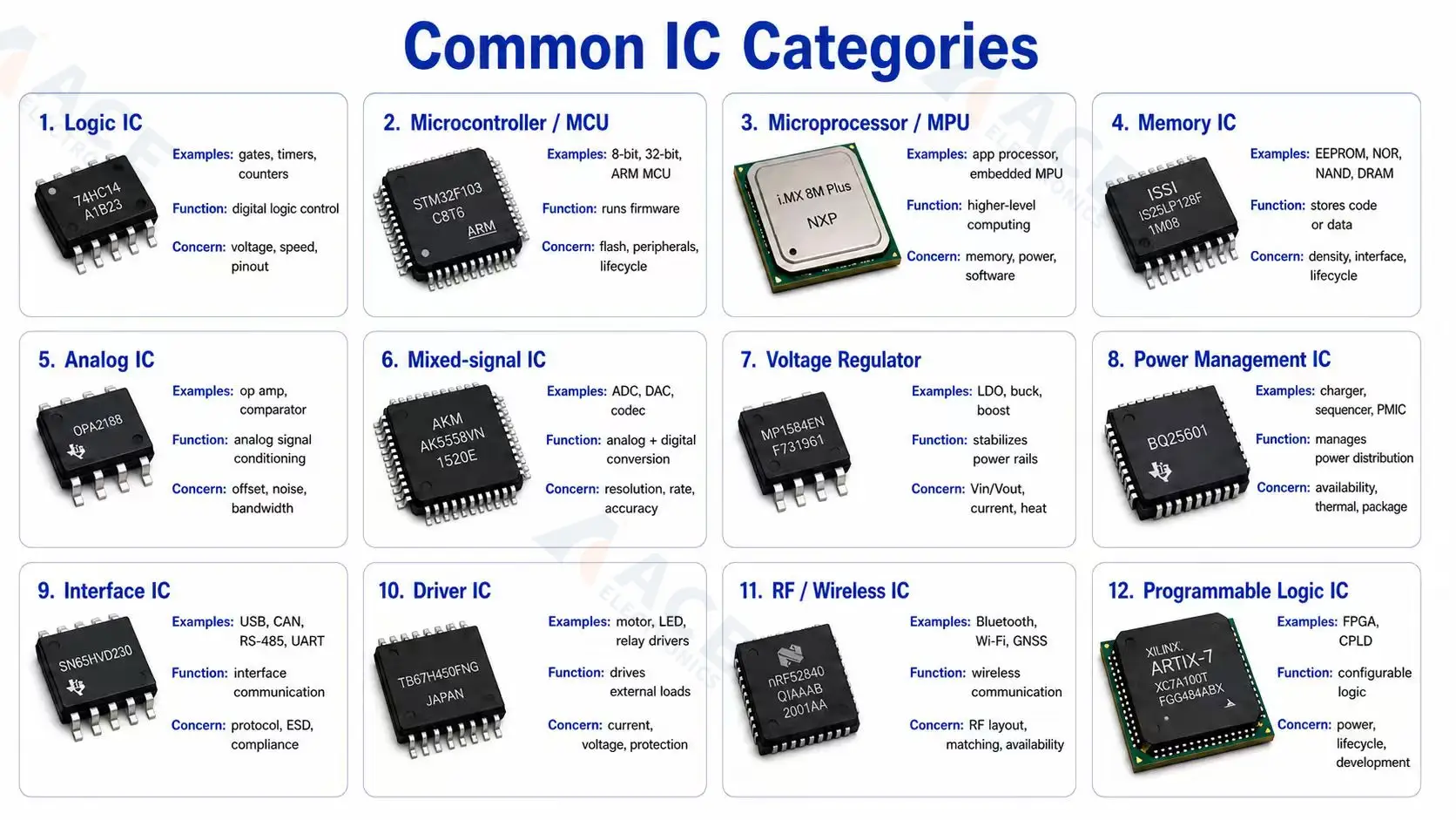
| IC Category | Typical Examples | Typical Function | Common Sourcing Concern |
|---|---|---|---|
| Logic IC | Logic gates, timers, counters, registers, level shifters | Handles basic digital logic and signal control | Logic voltage, package, pinout, speed, availability |
| Microcontroller / MCU | 8-bit, 32-bit MCU, ARM-based MCU | Runs firmware and controls product functions | Flash/RAM size, package, peripherals, firmware loading, lifecycle |
| Microprocessor / MPU | Application processor, embedded processor | Handles higher-level computing or operating-system-based control | Memory interface, power design, package, lifecycle, software support |
| Memory IC | EEPROM, NOR flash, NAND flash, DRAM, SRAM | Stores firmware, configuration, or data | Density, interface, speed, voltage, package, lifecycle |
| Analog IC | Op amp, comparator, instrumentation amplifier | Amplifies, compares, or conditions analog signals | Supply voltage, offset, bandwidth, noise, package |
| Mixed-signal IC | ADC, DAC, codec, sensor interface IC | Converts or processes both analog and digital signals | Resolution, sampling rate, interface, accuracy, supply voltage |
| Voltage regulator | LDO, buck converter, boost converter | Converts or stabilizes power rails | Input/output voltage, current, efficiency, heat, package |
| Power management IC | Battery charger, power sequencer, PMIC | Manages battery, charging, sequencing, and power distribution | Availability, thermal design, package, qualification |
| Interface IC | USB, Ethernet, CAN, RS-485, I2C, SPI, UART transceiver | Connects different communication interfaces | Protocol support, pinout, ESD rating, compliance, availability |
| Driver IC | Motor driver, LED driver, relay driver, MOSFET gate driver, display driver | Drives external loads or power devices | Output current, voltage rating, heat, package, protection features |
| RF / Wireless IC | Bluetooth, Wi-Fi, GNSS, RF front-end, transceiver | Handles wireless or RF communication | Certification impact, RF layout, antenna matching, availability |
| Programmable logic IC | FPGA, CPLD | Provides configurable digital logic | Package, programming file, lifecycle, power, development support |
ICs often carry sourcing and lifecycle risk, so package, pinout, supply voltage, interface, firmware needs, and availability should be checked early.
IC Selection Parameters
| Parameter | What to Check | Why It Matters |
|---|---|---|
| IC function | MCU, memory, regulator, interface IC, driver IC, RF IC, or analog IC | Different ICs serve different roles and cannot be replaced only by package or price |
| Package and pinout | QFN, QFP, BGA, SOIC, DFN, footprint, and pin arrangement | Affects PCB compatibility, assembly process, and whether a substitute is drop-in |
| Supply voltage | Operating voltage and input/output voltage range | The IC must match the product power rails and signal levels |
| Interface / protocol | I2C, SPI, UART, USB, Ethernet, CAN, RS-485, or other interfaces | Ensures communication compatibility with the rest of the circuit |
| Firmware / programming | Firmware file, programming method, memory size, and boot mode | Important for MCUs, flash memory, FPGAs, and programmable devices |
| Performance parameters | Speed, bandwidth, accuracy, resolution, current, or output power | Key performance requirements depend on the IC type |
| Thermal performance | Power dissipation, thermal pad, package, and PCB copper area | Prevents overheating, especially for power ICs, drivers, and processors |
| Lifecycle and availability | Active, NRND, obsolete, lead time, and second source options | Helps avoid production delays and redesign risk |
| Qualification / reliability grade | AEC-Q100, automotive grade, industrial grade, or other requirements | Required for automotive, industrial, outdoor, or long-life products |
Lifecycle and Availability Risks
Buyers should check whether key ICs are active, NRND, obsolete, or subject to long lead times. If an alternate is needed, the review may involve firmware compatibility, pinout, package, register behavior, electrical ratings, and test coverage.
Examples of common IC manufacturers include Texas Instruments, STMicroelectronics, Microchip, NXP, Analog Devices, Renesas, Infineon, onsemi, and Silicon Labs.
Connectors, Relays, Switches, and Electromechanical Parts
Electromechanical parts are components that combine electrical function with mechanical structure or movement. Common examples include connectors, relays, switches, sockets, terminals, and cable assemblies. These parts are important because they affect not only electrical performance, but also mechanical fit, assembly, durability, sourcing, and final product reliability.
Connectors, relays, and switches should be checked for footprint, height, orientation, contact rating, and mating-part availability.
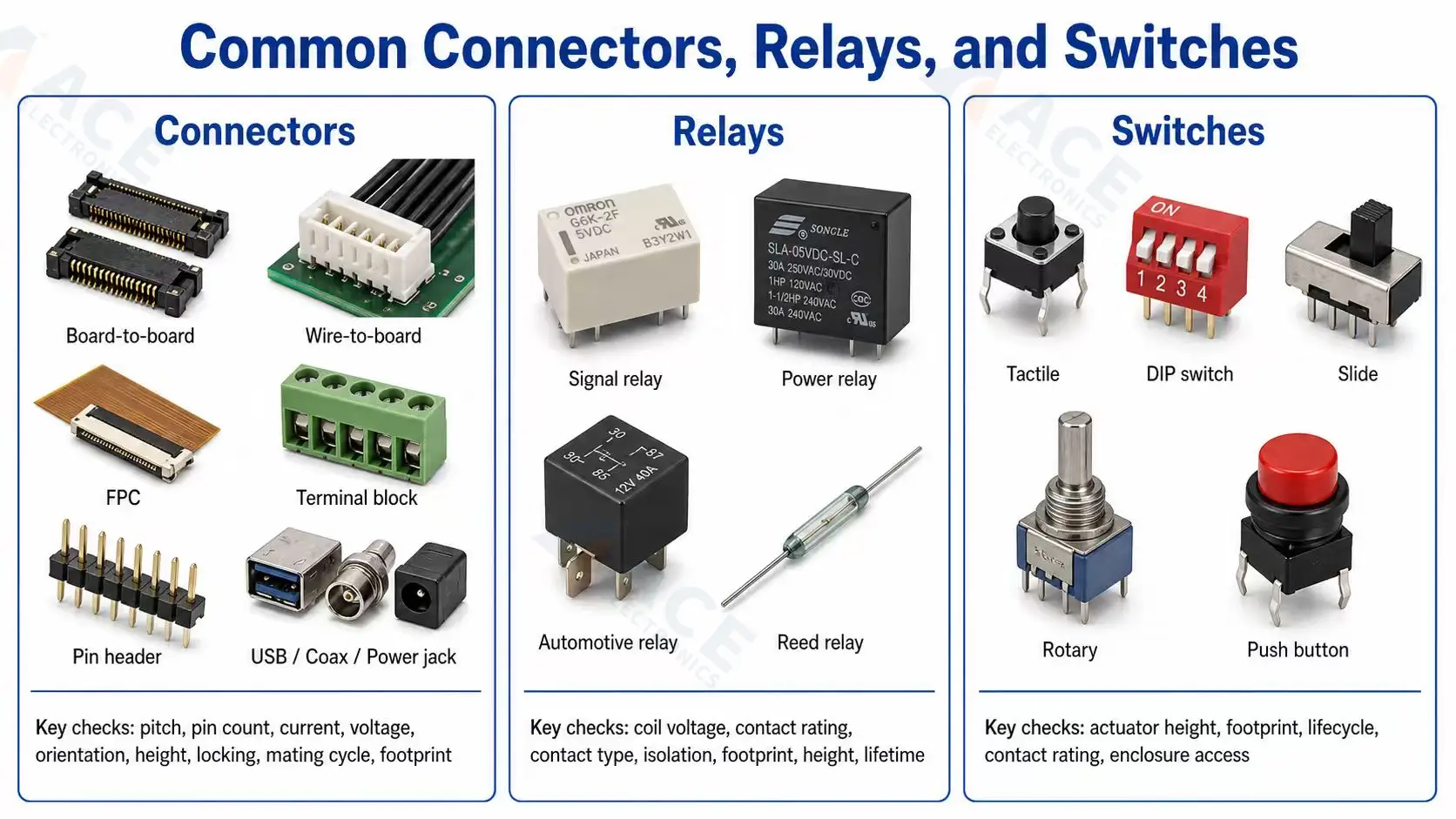
Connectors
Connectors include board-to-board connectors, wire-to-board connectors, FPC connectors, terminal blocks, pin headers, USB connectors, coax connectors, power jacks, and custom interface connectors.
Important selection parameters include pitch, pin count, current rating, voltage rating, orientation, height, locking style, mating cycle, contact material, operating temperature, footprint, and mating part availability.
Relays and Switches
Relays switch isolated or higher-power circuits. Selection parameters include coil voltage, contact rating, contact type, isolation, footprint, height, and mechanical lifetime.
Switches provide user input or configuration. Tactile switches, DIP switches, slide switches, rotary switches, and push buttons must be checked for actuator height, footprint, lifecycle, contact rating, and enclosure access.
Examples of common connector and electromechanical manufacturers include TE Connectivity, Molex, Amphenol, JST, Hirose, Phoenix Contact, Omron, Panasonic, C&K, and E-Switch.
Oscillators, Sensors, Fuses, and Other Circuit Board Parts
Some components do not fit neatly into passive or active categories, but they still affect sourcing and product function.
Timing, sensing, and protection components often require review for accuracy, calibration, exposure, current rating, isolation, and package constraints.
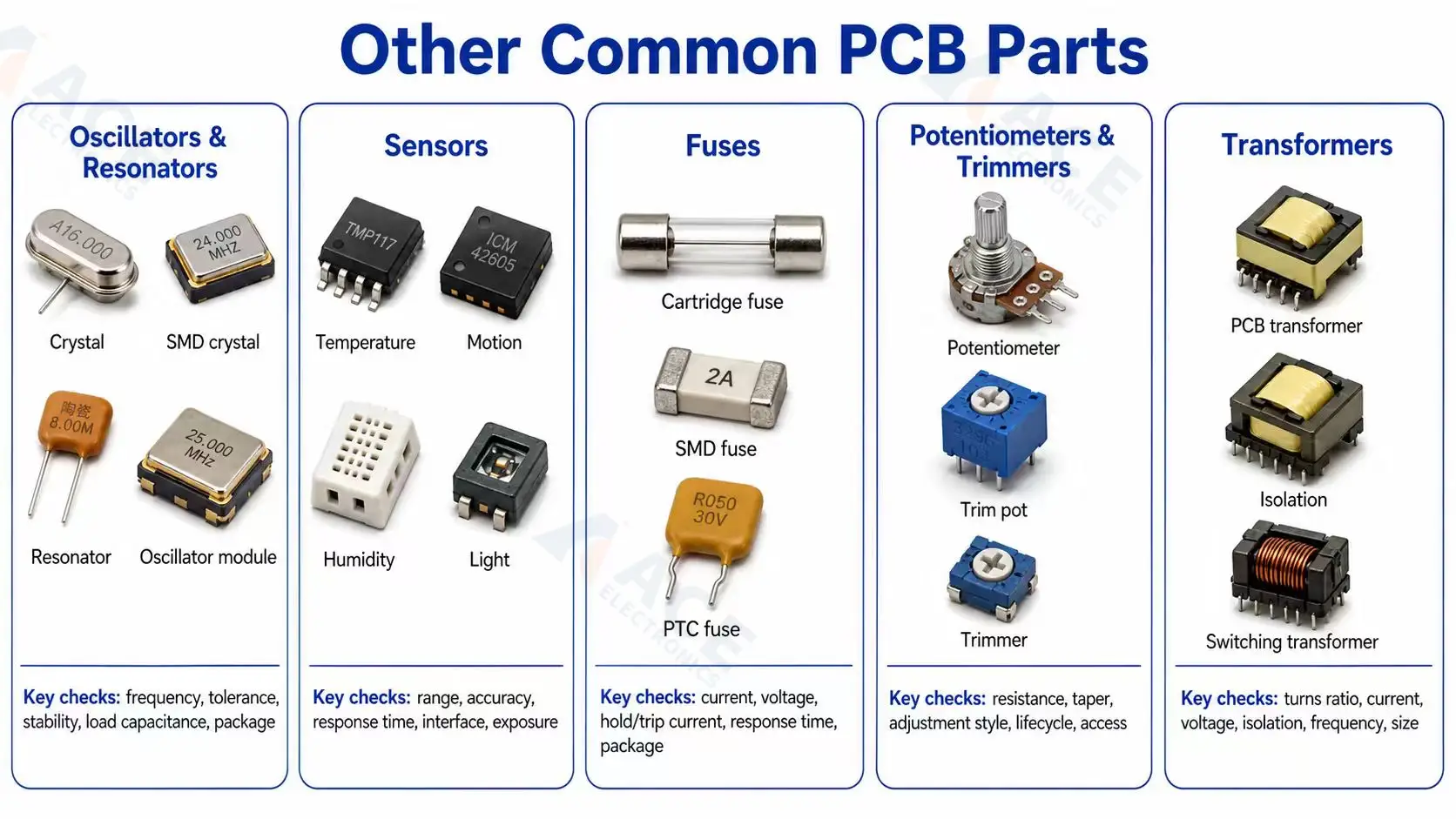
Crystal Oscillators and Resonators
Crystals, resonators, and oscillator modules provide timing references. Selection parameters include frequency, tolerance, stability, load capacitance, operating temperature, package, and aging.
Timing parts can affect communication, clock accuracy, and product certification. A replacement should be reviewed against the IC datasheet and layout requirements.
Sensors
Sensors detect temperature, pressure, motion, humidity, light, current, position, gas, or other physical inputs. Selection parameters include range, accuracy, response time, interface, calibration, operating temperature, package exposure, and lifecycle.
Some sensors must remain exposed to air, light, motion, or pressure. They may be affected by coating, enclosure design, or placement near heat sources.
Fuses and Resettable Fuses
Fuses protect the circuit from overcurrent. One-time fuses and resettable PTC fuses behave differently. Important parameters include current rating, voltage rating, trip current, hold current, response time, resistance, temperature derating, and package.
Potentiometers and Transformers
Potentiometers and trimmers provide adjustable resistance. Check resistance value, taper, adjustment style, lifecycle, and access after assembly.
Transformers provide energy transfer, voltage conversion, signal coupling, or isolation. Check turns ratio, current, voltage, isolation rating, frequency range, size, and safety spacing.
Examples of manufacturers in these categories include Abracon, Epson, TXC, Littelfuse, Bel Fuse, Bourns, Honeywell, Bosch Sensortec, Sensirion, TDK, and Murata.
SMT, Through-Hole, and Package Selection
SMT and through-hole choices affect sourcing and package compatibility. SMT components are mounted directly on surface pads. Through-hole components use leads inserted into plated holes. Both can be valid, but they are not interchangeable without PCB footprint changes.
SMT Components
SMT parts support compact layouts and automated placement. Common packages include 0201, 0402, 0603, 0805, SOT-23, SOIC, TSSOP, QFN, QFP, and BGA. Small packages and fine-pitch parts need correct footprint data and clear sourcing alternates.
See ACE's SMT assembly page for process capability context.
Through-Hole Components
Through-hole parts are common for connectors, relays, transformers, terminals, large capacitors, and parts that need stronger mechanical retention. Through-hole package substitutions should be checked for lead spacing, pin diameter, body size, and height.
See ACE Electronics's through-hole assembly page for assembly context.
Package vs Footprint
A package describes the physical component. A footprint describes the PCB land pattern. A 10 kOhm resistor in 0603 and a 10 kOhm resistor in 0402 may have the same electrical value but cannot be placed on the same footprint.
Package substitutions should be reviewed before the BOM is approved. If the package changes, the PCB layout may need revision. A PCB design and DFM review can help confirm footprint compatibility before sourcing and placement.
How to Identify Circuit Board Components
Circuit board components can be identified by reference designators, silkscreen markings, top markings, package shape, polarity marks, BOM data, and datasheets. For sourcing decisions, visual identification is only a starting point. The BOM and datasheet should confirm the exact part.
Reference designators connect physical components with the BOM and schematic.
| Designator | Component Type |
|---|---|
| R | Resistor |
| C | Capacitor |
| L | Inductor |
| FB | Ferrite bead |
| D | Diode or LED |
| Q | Transistor or MOSFET |
| U or IC | Integrated circuit |
| J, CN, or P | Connector |
| Y or X | Crystal or oscillator |
| F | Fuse |
| K or RL | Relay |
| SW | Switch |
| TP | Test point |
| T | Transformer |
Silkscreen markings can help match components to the BOM, but they are not always complete. Small SMT components may have no readable marking. IC top codes can be manufacturer-specific. Connector markings may identify a series but not the exact variant.
For production sourcing, confirm the component through the BOM, schematic, PCB footprint, datasheet, and approved alternates. Do not rely only on photos or visual inspection when approving substitutes.
Component Sourcing and Approved Alternatives
Component sourcing should start before a prototype or production run reaches the quote stage. Early sourcing review helps identify obsolete parts, long lead-time ICs, limited-availability connectors, unclear alternates, package mismatches, and compliance gaps.
What Makes a Component Hard to Source
Components are more likely to create sourcing issues when they are:
- obsolete or NRND
- controlled by allocation
- available from limited suppliers
- available only in a different package
- tied to firmware or certification
- custom or semi-custom
- high-value or shortage-sensitive
- missing a manufacturer part number
- specified only by a distributor SKU
- missing approved alternatives
When a Substitute Is Not Really Equivalent
Before sourcing, share the BOM, preferred brands, approved alternatives, and any parts that must stay unchanged. ACE Electronics can help review these requirements as part of turnkey component sourcing.
Assembly and Testing Notes That Matter for Component Selection
Assembly and testing requirements can change whether a component is practical to use, especially when the part is polarized, hidden after soldering, firmware-controlled, coating-sensitive, or constrained by an enclosure.
Polarity and Orientation
Diodes, LEDs, electrolytic capacitors, tantalum capacitors, ICs, connectors, battery holders, and some sensors need clear orientation. If polarity is unclear, the assembly partner must stop and ask for confirmation.
Inspection Requirements
Some packages need extra inspection planning. BGAs have hidden solder joints and often require X-ray inspection. QFNs may need thermal pad review. Fine-pitch ICs need careful placement and solder paste control.
Firmware Loading and Functional Test Considerations
Microcontrollers, memory devices, communication ICs, and some sensor modules may require firmware loading or functional testing. If this applies, the BOM review should identify which components need loading access, test coverage, or calibration; see firmware loading and functional testing for the related process.
Coating and Enclosure Constraints
Sensors, connectors, switches, test points, LEDs, displays, buzzers, and mechanical contacts may need coating restrictions or masking. Component height and connector access can also affect final product assembly or enclosure fit. For coated PCBAs, see conformal coating.
Conclusion
Circuit board components should be reviewed by function, type, package, rating, sourcing status, and approved-alternative options. The review should confirm whether each part can be sourced, placed, inspected, substituted, and supported through the product lifecycle.
Review component risk before the BOM is frozen. Clear manufacturer part numbers, package data, ratings, approved alternates, and sourcing notes make the later quotation and production process more predictable.
Frequently Asked Questions
What are the most common circuit board components?
What are the most common circuit board components?
The most common circuit board components include resistors, capacitors, inductors, diodes, LEDs, transistors, MOSFETs, integrated circuits, connectors, oscillators, relays, switches, fuses, sensors, and protection devices. Most PCBAs use a mix of passive components, active semiconductors, interface parts, and electromechanical components.
Which parameters matter most when selecting capacitors?
Which parameters matter most when selecting capacitors?
Important capacitor selection parameters include capacitance, voltage rating, tolerance, dielectric, ESR, ripple current, temperature rating, package size, polarity, and lifetime. For MLCCs, DC bias behavior should also be checked because the effective capacitance can drop under operating voltage.
What is the difference between an inductor and a ferrite bead?
What is the difference between an inductor and a ferrite bead?
An inductor is usually selected for energy storage, filtering, or current smoothing. A ferrite bead is usually selected for high-frequency noise suppression. They may look similar in a BOM, but they are not direct substitutes because their frequency behavior and key ratings are different.
Why are connector substitutions difficult?
Why are connector substitutions difficult?
Connector substitutions are difficult because pitch, pin count, height, orientation, latch style, mating part, contact plating, footprint, and mechanical fit must all match. A connector with the same number of pins may still fail to fit the PCB, cable, enclosure, or mating connector.
Which components are most likely to cause sourcing delays?
Which components are most likely to cause sourcing delays?
ICs, special connectors, power devices, sensors, relays, transformers, custom parts, obsolete parts, and components without approved alternates are more likely to cause sourcing delays. These parts should be checked early for lifecycle status, lead time, package availability, and substitute options.
How should approved component alternatives be reviewed?
How should approved component alternatives be reviewed?
Approved alternatives should be reviewed for electrical value, voltage and current ratings, tolerance, package, footprint, pinout, lifecycle status, compliance, thermal behavior, and test impact. A substitute should not be approved only because it has a similar value or appears in the same product category.
Why do component packages matter in BOM review?
Why do component packages matter in BOM review?
Component packages matter because the physical part must match the PCB footprint. A package change can affect pad fit, height, polarity, solder joint quality, inspection, and enclosure clearance. Package substitutions should be reviewed before purchasing or assembly starts.
How do you identify circuit board components from reference designators?
How do you identify circuit board components from reference designators?
Reference designators identify component locations and types on a PCB. Common examples include R for resistor, C for capacitor, L for inductor, D for diode or LED, Q for transistor, U or IC for integrated circuit, J or CN for connector, and F for fuse.
Which components need polarity or orientation checks?
Which components need polarity or orientation checks?
Diodes, LEDs, electrolytic capacitors, tantalum capacitors, ICs, connectors, battery holders, relays, and some sensors need polarity or orientation checks. The PCB silkscreen, assembly drawing, BOM, and datasheet should provide consistent orientation information.
Which components usually need extra inspection or testing?
Which components usually need extra inspection or testing?
BGAs, QFNs, fine-pitch ICs, power devices, polarized components, connectors, sensors, safety-related protection parts, and firmware-controlled ICs often need extra inspection or testing. Some may require X-ray inspection, functional testing, firmware loading, calibration, or coating clearance review.