Flex & Rigid-Flex PCB Manufacturer
From prototype to Mass Production
15 Years Manufacturing & Engineering Experience keep Your projects stable quality
3-6 days quick lead time smooth Your production.
IPC-6012 Class 2/3 compliant Flex & Rigid-Flex manufacturing with AOI, 100% E-test.


Our Flex & Rigid-Flex Capabilities
From dynamic flexible circuits to complex rigid-flex structures, we ensure durability and precision.
| Feature | Flex PCB (FPC) | Rigid-Flex PCB |
|---|---|---|
| Layer Count | 1 - 6 Layers | • Rigid: up to 20 Layers (HDI available) • Flex Area: 1–6 Layers |
| Base Material | Polyimide (PI), Polyester (PET) | PI + High-Tg FR-4 (Tg170–180) |
| Copper Type | Rolled Annealed (RA) / Electro-Deposited (ED) | RA (for flex area) + ED (for rigid area) |
| Board Thickness | 0.08mm - 0.4mm | Flex: 0.06–0.25 mm (depending on layer count) Rigid: 0.4mm - 2.4mm |
| Min. Trace / Space | 3mil / 3mil | 3mil / 3mil HDI: down to 2/2 mil |
| Min. Drill Size | Laser via: 0.075–0.1 mm Mechanical drill: ≥0.2 mm |
0.2mm (Through-hole) 0.1mm (Blind) |
| Coverlay / Mask | PI Coverlay (Yellow/Black/White) | PI Coverlay + Liquid Photoimageable (LPI) Mask |
| Stiffeners | FR4, Polyimide, Aluminum, Stainless Steel (304) | Rigid sections act as structural stiffeners. Additional local stiffeners available if required |
| Min. Bending Radius | Static bend: • Single layer: ≥6×T • Multilayer: ≥10–15×T Dynamic bend:• ≥100×T (RA copper required) |
Flex Area: ≥10×Thickness depending on layer count |
| Surface Finish | ENIG (Most Common) | ENIG, Immersion Tin, OSP |
Critical Design Rule
To prevent cracking in dynamic applications (e.g., robotics, hinge cables), please use Rolled Annealed (RA) Copper and ensure grain direction is perpendicular to the bend.
Flexible PCB Manufacturing Process
Strict quality control from raw material to finished product.
Cases Study For Your Reference

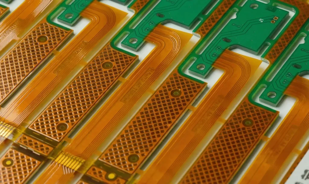
2 Layers Rigid-Flex PCB
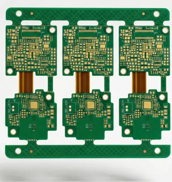
12-Layer 4-Stage HDI Rigid-Flex

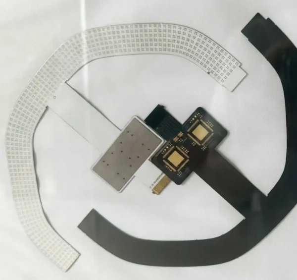
Medical ENIG Area FPC
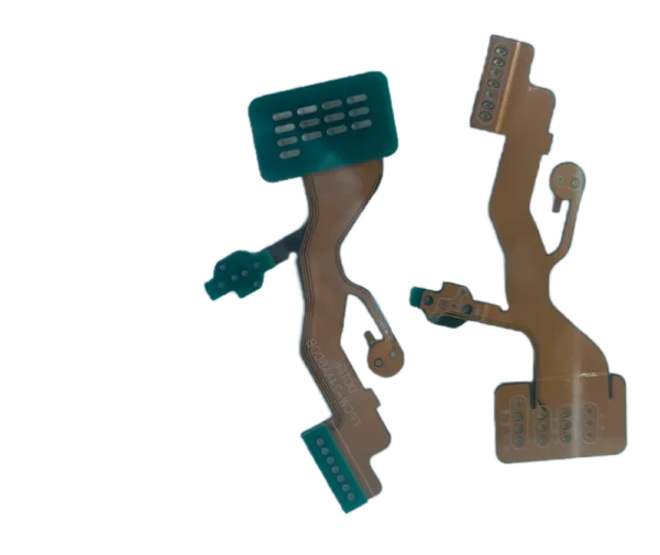
Automotive 6 layers 2+N+2 HDI Rigid-flex PCB
2 layers Rigid-Flex PCB
Why Partner With ACE Tech?
IPC Class 3 Standard
We don't just meet standards; we exceed them. Dedicated production lines for automotive and medical PCBs.
Quick Turnaround
24-hour expedited service for double-sided boards, 48-72 hours for multilayers. Speed without compromising quality.
Cost-Effective
Direct factory pricing with smart panelization suggestions to minimize waste and reduce your BOM cost.
Advanced Technology
Capable of 3mil trace/space, blind/buried vias, and controlled impedance for high-speed signals.
Expert Engineering
Dedicated CAM engineers review every file. We catch design errors before they become manufacturing defects.
Global Logistics
Seamless shipping to Europe and North America via DHL/FedEx/UPS, with DDP options available.
How You Order PCB
From Gerber files to your doorstep (or assembly line) in 6 simple steps.
Upload Files
Gerber RS-274X & BOM
Free DFM Check
Within 12 Hours
PCB Fabrication
Quick Turn / Mass Prod
Electrical Test
100% E-Test / AOI
FQC & Packing
Final QC / Vacuum Pack
Ship or Assembly
Global Delivery / ACE Electronics SMT Lines
Where Flex & Rigid-Flex PCBs Excel
From medical devices to aerospace, flexible circuits solve space and reliability challenges.
Medical Devices
Endoscopes, hearing aids, and patient monitoring systems requiring biocompatible materials and extreme reliability.
Automotive Electronics
Instrument clusters, ABS systems, and EV battery management requiring high-temperature resistance and vibration durability.
Wearables & Mobile
Smart watches, foldable phones, and AR/VR headsets where space is critical and dynamic flexing is required.
Industrial & Robotics
Robotic arms, automation equipment, and sensor arrays requiring millions of flex cycles and chemical resistance.
Flex & Rigid-Flex PCB FAQs
Q
What is the minimum bending radius for flex PCBs?
What is the minimum bending radius for flex PCBs?
For static applications (installed once), the rule is ≥6× thickness for single-layer, ≥10× for multilayer. For dynamic applications (repeated movement), use ≥100× thickness and specify Rolled Annealed (RA) copper with grain direction perpendicular to the bend.
Q
Can rigid-flex boards have HDI features?
Can rigid-flex boards have HDI features?
Yes. Our rigid-flex capabilities include blind and buried vias in the rigid sections, laser microvias down to 0.075mm, and any-layer interconnection. The flexible sections typically use through-holes or blind vias due to material constraints.
Q
Polyimide vs. PET: Which should I choose?
Polyimide vs. PET: Which should I choose?
Use Polyimide (PI) for high-temperature applications (>105°C), soldering, or when flame resistance is required. Use PET only for low-cost consumer electronics with no soldering and operating temperatures below 80°C.
Q
How do you prevent via cracking in rigid-flex boards?
How do you prevent via cracking in rigid-flex boards?
We use plated via filling (copper or epoxy) in rigid sections, avoid vias in the flex bend area, and use tear-drops at trace-via junctions. For high-reliability applications, we recommend blind vies in flex areas rather than through-holes.
Other Services Available At ACE Electronics
From PCB fabrication to fully assembled products. Streamline your supply chain with our integrated manufacturing services.
PCB Assembly
SMT and THT assembly with 01005 component capability. Complete with AOI, X-ray inspection, and IC programming.
Explore PCBA ServicesParylene Coating
In-house CVD parylene coating for ultimate moisture and chemical protection. Ideal for medical devices and harsh environments.
Learn About Parylene CoatingBox Build Assembly
Complete electromechanical integration: enclosures, cable harnesses, PCB mounting, and functional testing to finished product.
View Box Build ServiceNeed a complete manufacturing partner?
Explore All Turnkey ServicesStart Your Projects Manufacturing Today!
Whether you need a quick quote or technical consultation, we're here to help.
Quick Response via WhatsApp
Get instant answers to your questions
Connect directly with our technical team for immediate assistance.
We typically respond within 30 minutes during business hours.
Business Hours: Mon-Fri 9:00-18:00 (GMT+8)