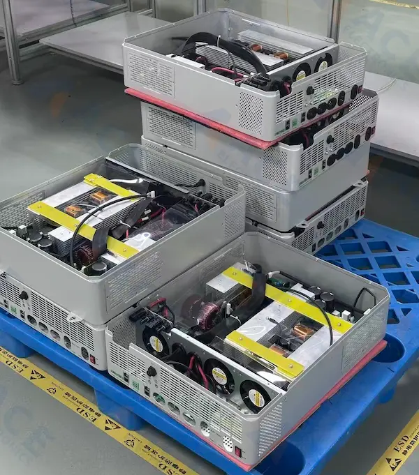
We supported this project as a turnkey manufacturing partner for an industrial and commercial energy storage inverter. Our scope covered component sourcing, PCB assembly, custom transformer coordination, wire harness and cable assembly, final box build assembly, finished product testing, and packaging.
The customer wanted one supplier instead of several. That made overall quality control easier and reduced the time and labor needed to coordinate different vendors. For a product like an energy storage inverter, the board, the internal wiring, the chassis, and the finished product test all affect the final result. Managing these steps under one production flow made the project easier to control.
During prototyping, we found one key risk early. Several large heatsinks on the power board were fixed in a way that could create stability problems during transport and long-term use. We raised the issue, proposed a simple insulated support bar, and discussed it with the customer. After the customer accepted the change and the samples passed verification, the new fixing method became part of the mass production standard.
This cooperation has now continued for two years, with monthly output reaching 500 units. In this article, we focus on the practical parts of the project: why the customer chose a turnkey model, how we handled the full production scope, how we improved heatsink fixing, how we managed custom transformer sourcing, and how we verified each batch before shipment.
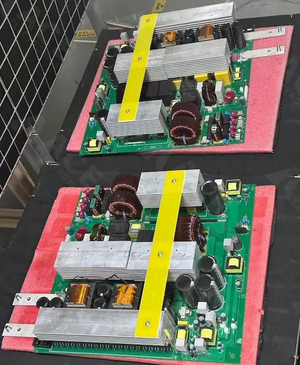
Top-side view of an industrial and commercial energy storage inverter power board with large aluminum heatsinks, copper-wound inductors, electrolytic capacitors, and an insulated yellow support bar used to stabilize the heatsink assembly.
Project Snapshot
- Product: Industrial and commercial energy storage inverter
- Manufacturing model: Turnkey production
- Scope: Component sourcing, PCB assembly, custom transformer coordination, wire harness processing, chassis assembly, finished product testing, and packaging
- Main build risk: Stability of large heatsinks during transport and long-term operation
- Key sourcing issue: Supplier matching and price control for custom wound transformers
- Test flow: Sample board power-on test, overload test on 1 to 5 boards from each monthly batch, routine power-on test for every board, and 12-hour power-on aging test for each finished unit
- Production status: Two years of ongoing cooperation, 500 units per month
- Customer feedback basis: Failure rate below 1% within six months after shipment for each batch
Quick Summary: Key Challenges & Solutions
| Challenge | ACEPCBA Engineering Solution | Impact |
|---|---|---|
| Mechanical Instability | Engineered custom epoxy fiberglass support bars for high-mass heatsinks. | Eliminated transport vibration damage; zero shifting. |
| Thermal Management | Optimized thermal interface material (TIM) application and clearance verification. | Maintained stable delta-T during peak operation. |
| Magnetics Sourcing | Audited & coordinated dedicated high-power transformer suppliers. | 15% cost reduction; 100% material traceability. |
| Reliability Risk | Implemented 4-stage testing: Sample -> Samples Overload -> Power-on Test -> 12H Burn-in Test | ≤1% Field Failure Rate over 6 months. |
The Strategic Advantage of Turnkey Manufacturing for Energy Storage Systems
The customer did not want to split this project across separate suppliers for board assembly, wire harness work, chassis assembly, and final testing. That kind of setup often creates more handoffs, more communication work, and more room for mistakes.
A turnkey model solved two direct problems.
First, it unified the production flow. The same manufacturing team could manage the build from incoming parts to finished unit delivery. This made overall quality control more consistent.
Second, it reduced communication cost and staffing cost on the customer side. The customer did not need to spend the same amount of time aligning multiple suppliers on schedule, revision changes, assembly details, and test requirements.
For buyers working on products in industrial automation device manufacturing, this is often the practical reason to move to a one-supplier model.
End-to-End Inverter Production: From PCBA to Full Box Build
This was not a board-only order. We supported the full build as a turnkey manufacturing project.
Our scope included:
- sourcing electronic parts and key electromechanical parts
- matching and coordinating a supplier for custom wound transformers
- PCB assembly for the inverter power boards
- wire harness processing
- chassis assembly
- finished product testing
- packaging before shipment
Because these steps were handled together, we could align the board build, internal wiring, mechanical assembly, and test flow in one controlled process. That is the main difference between a standard PCBA order and a turnkey PCBA contract manufacturing program with final integration.
The Main Mechanical Risk Found During Prototyping
During prototyping, we found a risk in the original fixing method for several heatsinks on the power board.
These heatsinks were long and relatively heavy. If they were fixed only by bottom screws, they could shift or tilt during transport vibration. Long-term heating and cooling cycles could also affect their stability over time. On a high-power board, that kind of movement is not a small detail. The heatsinks sit close to large capacitors, coils, transformers, and other important parts, so position control matters.
We raised this issue during the sample stage instead of waiting for volume production to expose it later. That early review made it possible to solve the problem before the build moved into stable monthly output.
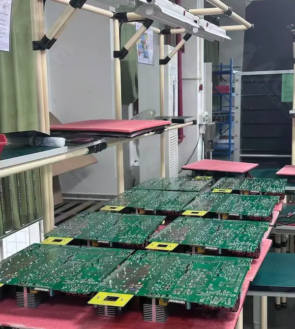
Bottom-side view of industrial and commercial energy storage inverter PCBs staged for batch processing in production, showing assembled boards with dense solder joints and high-power inverter board construction.
Solving Thermal Challenges: Our Custom Support Solution for High-Power Heatsinks
Our engineering team proposed adding a custom epoxy fiberglass support bar across several heatsinks. We discussed the change with the customer, confirmed acceptance, and then verified the solution during sample testing. After the samples passed, the support bar was introduced into the mass production standard.
This change solved several problems at the same time.
1. Better Mechanical Stability
The support bar linked several heatsinks together instead of leaving each one dependent only on its own bottom screws. That improved overall rigidity and reduced the risk of shifting or leaning during transport.
2. Electrical Insulation
In power electronics, a heatsink may not always be at ground potential. A direct metal crossbar could create a short-circuit risk. Using an insulated material avoided that problem.
3. More Even Fixing Force
The support bar helped keep pressure more even across the heatsinks. It reduced the risk of one heatsink being too tight while another was too loose.
4. Better Position and Spacing Control
The added support helped keep the heatsinks in place during assembly and use. It also helped maintain safe spacing from nearby capacitors, coils, and transformers.
5. Lower Cost and Simpler Process
A simple insulated bar and a few screws solved fixing, insulation, and positioning together. This was cheaper and easier to implement than adding a more complex metal bracket.
If a project includes special mounting details on the board itself, our tech guide on counterbore vs countersink holes in PCB design may also help clarify mechanical choices during early DFM review.
Custom Transformer Sourcing for Volume Production
Another important part of this project was custom transformer sourcing.
The main issue was not only finding a supplier that could produce according to the customer’s drawing. We also needed a supplier match that worked for stable monthly production and reasonable cost. That meant balancing technical fit with price control.
We coordinated with a qualified transformer supplier based on the customer’s design requirements. After the transformers arrived, they were soldered onto sample boards and tested in the real circuit. This step mattered because it verified the sourced parts in actual use instead of only checking them as incoming material.
That process reduced sourcing risk before regular production started. It also helped the customer avoid spending extra time and labor on supplier coordination for a key custom part.
Rigorous 4-Stage Testing: Ensuring Zero-Defect Performance for Industrial Inverters
Testing was built into the process at several stages.
First, during the sample stage, we powered on and tested the board.
Second, for each monthly production batch, we selected 1 to 5 boards for overload testing under strict conditions. The goal was to verify the components used in that batch and catch any issue tied to lot variation before it could affect more units.
Third, every board went through a routine power-on test on the test fixture. This checked normal electrical function before final assembly.
Fourth, after final assembly, every finished inverter went through a 12-hour power-on aging test. This allowed us to check both the circuit and the assembled product in operating condition. It also helped confirm that related parts such as fan connections and other interfaces were working as expected.
This test flow gave the project more than one control point. It checked the sample, the production batch, the assembled board, and the finished product before shipment.
For products that also need environmental protection after electrical verification, readers can refer to our blog article on how to choose the right conformal coating for your PCBA.
Proven Reliability: Achieving a ≤1% Field Failure Rate Over 6 Months
This project has now been in cooperation for two years, with monthly output reaching 500 units.
During in-house testing, about 1.2% of units were intercepted, repaired, and retested before shipment. All shipped products completed the required test process before delivery.
Based on customer feedback, the failure rate within six months after shipment has remained below 1% for each batch.
These results came from the whole process working together. The sourcing work, the heatsink fixing improvement, the wire harness build, the final assembly process, and the test flow all contributed to stable production.
What This Means for Energy Storage Equipment Manufacturer
For an energy storage inverter, manufacturing risk does not sit in one step alone.
Board assembly matters, but it is only part of the job. Heavy parts need stable fixing. Custom magnetic parts need the right supplier and real sample verification. Internal wiring needs to match the final product build. Finished units need to be tested as complete products, not treated as a simple collection of parts.
That is why a turnkey approach can make sense for this kind of project. When one manufacturing team manages sourcing, assembly, integration, and testing together, the process becomes easier to control.
Conclusion
We supported this industrial and commercial energy storage inverter project with component sourcing, custom transformer coordination, PCB assembly, wire harness processing, chassis assembly, finished product testing, and packaging.
The most important technical change happened early. We found a heatsink fixing risk during prototyping, proposed an insulated support bar solution, verified it with the customer through sample testing, and then introduced it into mass production. Combined with batch overload testing and finished unit aging tests, this helped build a more stable production process for long-term delivery.
If you are looking for a manufacturing partner for energy storage inverter PCBA, box build assembly, or complete product testing, ACE Electronics can support your project from sourcing to finished unit delivery.
+++FAQ+++
What is included in turnkey manufacturing for an energy storage inverter?
Turnkey manufacturing for an energy storage inverter typically includes component sourcing, PCB assembly, custom magnetic component coordination, wire harness and cable assembly, chassis or box build assembly, finished product testing, and packaging before shipment.
Why is heatsink fixing important in high-power inverter PCBs?
In high-power inverter PCBs, large heatsinks can shift during transport vibration or repeated thermal cycling if they are not fixed properly. Stable heatsink mounting helps protect nearby capacitors, magnetic components, and other critical parts while maintaining mechanical reliability over time.
Why was an insulated support bar added to the heatsink assembly?
An insulated support bar was added to improve mechanical stability, maintain safer spacing between components, and avoid the electrical short-circuit risk that could come from using a conductive metal support across multiple heatsinks.
How are custom transformers verified before mass production?
Custom transformers are usually verified through supplier qualification, incoming inspection, and sample validation in the actual circuit. Testing them on prototype or sample boards helps confirm real operating performance before regular production begins.
What testing was used for this energy storage inverter project?
This project used a 4-stage testing process: sample board power-on testing, overload testing on selected boards from each monthly batch, routine power-on testing for every board, and a 12-hour power-on aging test for every finished inverter unit.
Why do buyers choose turnkey manufacturing for industrial energy storage equipment?
Buyers often choose turnkey manufacturing to reduce supplier coordination work, improve quality control across multiple production stages, shorten communication paths, and manage PCB assembly, wiring, mechanical assembly, and final testing within one controlled process.
+++FAQ+++
Author: Bill Ho, Sales Engineer & Chief Editor at ACE Electronics.
Industry Experience: 10 Years Experience in PCB Fabrication and PCB Assembly.
Have a project ready for manufacturing?
Fill out the form below and our engineering team will get back to you within 24 hours.